
Ribbon Blender Manufacturer: Troughs, Ribbons & Sanitary Builds From China
 ·
Updated October 13, 2026
·
27 min read
A ribbon blender is the plainest mixing machine in a powder plant: a long U-shaped trough, a shaft through the middle, and two ribbons wound around that shaft in opposite directions. It is bought on working volume and motor size, and it is accepted or rejected on three things the quotation almost never shows — whether the ribbons actually touch the material at the trough wall, whether the machine can be taken apart by the people who have to clean it, and whether a sample taken out of it means anything at all.
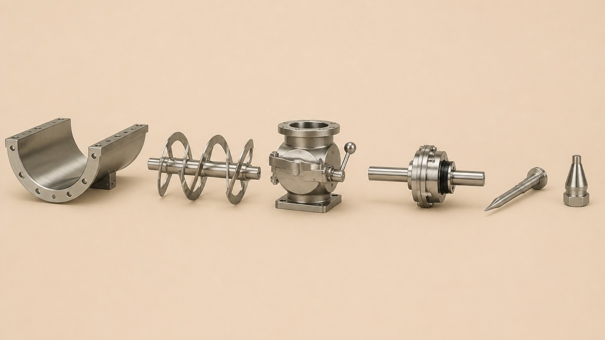
Six Lines That Decide Whether a Blender Order Is Complete
| What the buyer has to settle | Why it is not obvious | The line on your order that closes it |
|---|---|---|
| Working volume, not total volume | The two numbers differ by a large margin, and a quotation usually gives only one of them | Working volume at the stated fill, with the bulk density it was calculated on |
| Ribbon-to-wall clearance and ribbon pitch | These decide whether dry powder is swept off the floor or left standing in a dead band | Clearance and pitch as figures, not as the words heavy duty |
| Who takes it apart, and with what | The cleaning procedure has to describe how the machine is dismantled and rebuilt | Coupling, seal and discharge designed for removal by hand tools |
| Surface finish on every food-contact surface | The inside of the trough is easy to polish; the weld at the end plate and the underside of the shaft are not | A finish figure for each surface, written surface by surface |
| Where the sample is taken from | A uniformity figure with no sampling plan behind it cannot be repeated by anyone | Sample points, sample count and blend time, agreed before the run |
| What the factory makes and what it buys | The drive, the seals and a chopper or spray system are often bought in, and they set the lead time | A make-or-buy split with the maker named for each bought item |
What a Ribbon Blender Manufacturer Actually Sells You
A ribbon blender factory builds the trough, the ribbon set and the frame. It buys the gearbox and motor, the shaft seals, the discharge valve, and any spray or chopper system. The control panel is either built in house or bought as a package, and that choice is worth knowing because it decides who answers when the machine will not start on site.
The machine is usually described by its total volume, and that is the first place a price difference hides. A trough listed as one thousand litres holds somewhere between six and seven hundred litres of powder at a normal fill, because the ribbons have to lift and throw the material and they cannot do that in a trough packed to the top. A buyer comparing two quotations for a one thousand litre blender is often comparing two different working volumes, and nobody has said so.
The drive is the part most likely to be bought in, and it is worth naming in the enquiry for a practical reason: a ribbon blender starts under load, and the starting condition is what sizes the gearbox, not the running torque. A machine that has to start with a full trough of dense powder needs a different gearbox from one that starts empty, and a factory that quotes on running torque alone will deliver a machine that trips its overload every morning. The gearbox and motor are the two items on an industrial gear motor sized for the starting torque, not the running torque that decides whether the drive survives, so ask for the maker and the frame size rather than a kilowatt figure.
Then there is the train of equipment around the blender, and it belongs in the same enquiry because it decides whether the machine can be fed and emptied at the rate it was bought for. Powder arrives from above, usually from a bucket elevator that sets the infeed rate, and it leaves from a valve at the bottom into whatever comes next. Get the feed and discharge rates and the blender capacity is a paper number.
- The trough
- A U-shaped shell, usually stainless, with flat or slightly sloped ends. It carries the ribbons, the seals at each end, the discharge opening at the bottom and the lid. Its thickness and its stiffness decide whether it holds its shape under a full load.
- The ribbon set
- The shaft with its radial arms and the two helical ribbons. The outer ribbon runs close to the trough wall on the largest practical diameter, and the inner ribbon is wound the other way on a smaller diameter. Together they move material in two directions at once, which is the whole trick.
- The drive
- A gearbox and motor, usually flange mounted on one end plate, with a coupling or a direct shaft connection. This is where the starting load is absorbed.
- The discharge
- An opening at the lowest point of the trough with a valve on it, chosen for what the powder does — flow freely, bridge, or flood.
- The seals and the lid
- The two places the shaft passes through the trough wall, plus a lid that either keeps dust in or lets a person in. Both are cleaning decisions as much as mechanical ones.
The Two Ribbons, and Why the Geometry Decides the Blend
The ribbons are the machine. Everything else is a container, a drive and an opening, and a blender built with the wrong ribbon geometry will not mix properly no matter how large its motor is or how long it is left running.
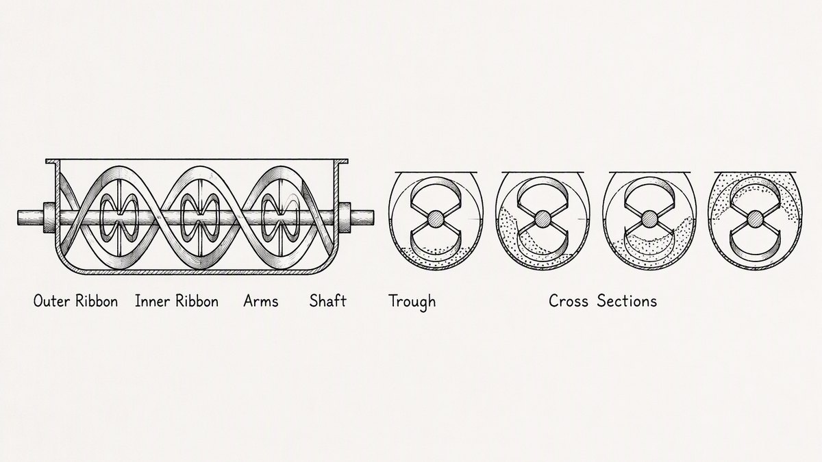
The outer ribbon is wound as a helix on the largest diameter that fits inside the trough, and it is pitched so that it pushes material in one direction along the length. The inner ribbon is wound the opposite way on a smaller diameter and pushes material the other way. Both are driven by the same shaft at the same speed, so the material is continuously split, sent to both ends and brought back. That counter-flow is what makes a ribbon blender work at all.
Three dimensions carry most of the result, and all three should appear as figures on the drawing rather than as adjectives.
- Ribbon-to-wall clearance
- The gap between the outer edge of the outer ribbon and the inside of the trough. Small enough and the ribbon sweeps the wall clean as it turns; too large and a standing layer of powder sits against the wall and never joins the blend. This is the single number that separates a blender from a bin with a stirrer in it, and it is the number a cheap quotation leaves out.
- Ribbon pitch
- How far one full turn of the helix advances the material. A shallow pitch moves material slowly and gently; a steep pitch moves it faster and works it harder. The choice follows the product, not the machine size, and it decides how long the blend takes.
- The ratio between the two ribbons
- Because both turn on one shaft, the outer ribbon travels much further per turn than the inner one. Their diameters and pitches have to be chosen together so that the two flows balance along the trough instead of piling material up at one end.
There is one more geometric fact worth knowing before a trough is ordered, because it explains a whole family of complaints. A ribbon blender has no high-shear zone. It moves material around rather than tearing it apart, and it does that well — gently, evenly, with very little heat and very little dust generation compared with a high-speed mixer. What it cannot do is break down a lump that formed upstream or disperse a liquid that has already turned into a sticky mass. When a plant reports that its blender will not break up agglomerates, the machine is usually working exactly as designed and the problem is somewhere else in the line.
The Working Volume, the Fill Level and the Paper Specification
Two volumes describe the same trough, and a quotation that gives only one of them cannot be compared with anything. Total volume is what the shell would hold if the lid were sealed and the trough filled to the top. Working volume is what it holds when it is loaded to the level the ribbons can actually work with, which is normally somewhere between half and three quarters of the total. The difference is not a rounding error; on a machine quoted as two thousand litres it can be several hundred litres of capacity a plant thought it was buying.
The working volume is not a fixed fraction either. It follows the product, and three properties decide it.
- Bulk density
- A light, fluffy powder fills the trough with very little mass, so the drive is barely loaded and the ribbons can turn a large volume. A dense mineral powder fills much less of the trough for the same mass, and a plant that buys on volume alone ends up with a machine that is overpowered in volume terms and underpowered in mass terms.
- How freely it flows
- A free-flowing granule settles into a low heap and can be worked at a higher fill. A poor-flowing powder builds a heap that the ribbons have to climb into, and the fill level has to come down so that the ribbons can reach the material at the top of the heap.
- What is being added
- Anything that goes in as a liquid takes up space without taking up much volume at the fill line, and a blend that starts as a dry powder and ends slightly damp will not fill the trough the way the dry powder did.
The practical instruction is simple and is the same instruction the product specification sheet exists to carry. Write the working volume down as a number and state the bulk density it was calculated on. A factory given a working volume and a density can size the trough, the ribbons and the drive together. A factory given a total volume will size the shell and guess the rest, and the guess will favour the smaller drive, because the drive is the expensive part. That is the whole mechanism by which a fully specified blender turns into an underpowered one.
There is one exception worth allowing for, and it comes from the material rather than the machine. If the feed arrives as a wet cake — the kind of damp, crumbly solid that comes off a filter press after the cake has been discharged — then the blender is being asked to break a cake into a powder rather than to blend two powders. That is a different duty, it needs a heavier ribbon and a stronger drive, and it needs to be said in the enquiry rather than discovered at commissioning.
How Mixing Actually Happens in a Trough
Ribbon blenders are described as convection mixers, which is a useful label because it says what they are good at. The ribbons lift material, carry it along the trough and drop it, and the counter-wound pair keeps two flows moving past each other the whole time. Nothing is cut and nothing is crushed. The blend comes from material being moved to different places, over and over, until the differences between one place and another are smaller than anyone can measure.
That mechanism explains the two things buyers most often get wrong about these machines.
The blend time is a property of the product and the geometry, not of the motor. Doubling the motor power does not halve the blend time; it only makes the same movement happen with more force available. If a blend takes twelve minutes and needs to take six, the answers are a different ribbon pitch, a smaller working volume so the ribbons reach everything sooner, or a different machine. A supplier who answers a blend-time complaint by quoting a bigger motor has misunderstood the machine, and the plant will find that out.
The end-to-end transfer matters as much as the circulation. Because the outer ribbon pushes one way and the inner ribbon pushes the other, material is constantly being carried from one end of the trough to the other and back. A trough that is too long for its diameter relies on that transfer for the whole blend, and length-to-diameter ratio is therefore a real design number. A very long, shallow trough can be made to mix, but it takes longer, because material at one end has further to travel before it meets material from the other.
Three practical consequences follow, and they are worth writing into the enquiry as requirements rather than discussing later.
- No dead zones along the wall or at the ends. The places where powder stops moving are the wall it does not touch, the corners where the trough meets its end plates, and the area directly above the discharge opening. Ask which of those the design addresses, and expect an answer about clearance and about the shape of the end plates.
- Fill level stated as a range, not a maximum. A blender works at its stated working volume and also at somewhat less. It does not work well at much less, because a shallow layer just gets pushed around without being lifted. If the plant intends to run half batches, say so, because it changes the ribbon design.
- Blend time quoted with the batch size it applies to. A blend time on its own is meaningless. It has to come with the fill level, the product, and whether anything was added during the run.
Cleanable Is a Design Duty, Not a Claim
Every quotation for a blender intended for food says the machine is easy to clean. That phrase has no agreed meaning and cannot be checked. There is, however, a rule that turns it into a list of things you can look at on a drawing, and it is worth reading in full because the obligations are placed on the equipment rather than on the cleaning crew.
The rule is 21 CFR 117.40, and it opens by making cleanability a design duty:
“All plant equipment and utensils used in manufacturing, processing, packing, or holding food must be so designed and of such material and workmanship as to be adequately cleanable, and must be adequately maintained to protect against allergen cross-contact and contamination.”
Then it rules out the things a blender can put into a product:
“Equipment and utensils must be designed, constructed, and used appropriately to avoid the adulteration of food with lubricants, fuel, metal fragments, contaminated water, or any other contaminants.”
It requires the equipment to be placed so that it can be reached:
“Equipment must be installed so as to facilitate the cleaning and maintenance of the equipment and of adjacent spaces.”
It fixes the material duty:
“Food-contact surfaces must be corrosion-resistant when in contact with food.”
“Food-contact surfaces must be made of nontoxic materials and designed to withstand the environment of their intended use and the action of food, and, if applicable, cleaning compounds, sanitizing agents, and cleaning procedures.”
And then it goes after the single feature of a welded trough that matters most:
“(b) Seams on food-contact surfaces must be smoothly bonded or maintained so as to minimize accumulation of food particles, dirt, and organic matter and thus minimize the opportunity for growth of microorganisms and allergen cross-contact.”
One more paragraph pulls in equipment the buyer may not have thought of as part of the machine at all:
“(d) Holding, conveying, and manufacturing systems, including gravimetric, pneumatic, closed, and automated systems, must be of a design and construction that enables them to be maintained in an appropriate clean and sanitary condition.”
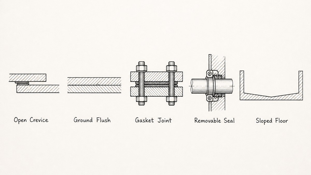
Read as a buyer, those paragraphs turn into five specific things to look at.
The weld where the trough meets the end plate. That is a food-contact seam, and the rule says it must be smoothly bonded. A continuous ground weld is a different piece of work from a tacked and sealed joint, and it is visible on the finished machine. Ask what the weld procedure is and whether the surface is ground after welding.
Every bolt, nut and thread inside the product zone. Exposed threads hold powder and cannot be cleaned. If a quotation shows ribs bolted to the inside of the lid, or a spray bar fixed with studs into the trough, the design has created places the crew cannot reach.
The slope of the trough floor toward the discharge. Liquid used for cleaning has to leave. A flat floor with a small opening in it leaves a puddle, and a puddle is a growth site. A gentle fall toward the low point is a fabrication decision made before the shell is rolled.
The shaft seal, as a removable part. This is the least visible and the most costly item on the list. A seal that has to be driven out of its housing, or a shaft that has to be cut free of a coupling to be withdrawn, means the deepest part of the machine cannot be cleaned or replaced without a workshop. A removable cartridge held by a clamp ring is the alternative, and it is a specification choice made at the order stage.
The lid, and what it is for. A lid that is welded shut is a cleaning problem. A lid that opens fully and stays open is a lid a person can work through. Ask for the opening size and whether it holds itself open, because a heavy lid that has to be propped is a lid that gets left closed.
When the Blender Goes Into a Drug Plant
A blender sold into a pharmaceutical plant is bound by a second set of rules, and they are stricter in a particular way: they are written about what the surface must not do to the product. Two sections carry most of the weight.
The first is 21 CFR 211.65, on equipment construction:
“(a) Equipment shall be constructed so that surfaces that contact components, in-process materials, or drug products shall not be reactive, additive, or absorptive so as to alter the safety, identity, strength, quality, or purity of the drug product beyond the official or other established requirements.”
“(b) Any substances required for operation, such as lubricants or coolants, shall not come into contact with components, drug product containers, closures, in-process materials, or drug products so as to alter the safety, identity, strength, quality, or purity of the drug product beyond the official or other established requirements.”
Three words in the first paragraph do a great deal of work. Reactive rules out an alloy chosen for price that will react with the product. Additive rules out a surface that gives something up — including a lubricant. Absorptive rules out a surface that holds onto the product and lets it go into the next batch, which is the failure that a surface finish figure is really about.
The second paragraph settles an argument that comes up on almost every pharmaceutical blender enquiry. If a shaft bearing, a bushing or a gearbox sits where product or powder can reach it, the lubricant inside it is now a potential contaminant, and the rule is written to forbid that outcome. The design answer is to keep the drive outside the product zone, sealed from it, or to use a material that needs no lubricant at the contact — and that is a decision made when the shaft and the end plate are designed.
The second section is 21 CFR 211.67, on cleaning and maintenance, and its fourth paragraph is the most useful procurement sentence in this article:
“(b) Written procedures shall be established and followed for cleaning and maintenance of equipment, including utensils, used in the manufacture, processing, packing, or holding of a drug product. These procedures shall include, but are not necessarily limited to, the following:”
The items that follow include responsibility, schedules, and then this one:
“(3) A description in sufficient detail of the methods, equipment, and materials used in cleaning and maintenance operations, and the methods of disassembling and reassembling equipment as necessary to assure proper cleaning and maintenance;”
And later:
“(6) Inspection of equipment for cleanliness immediately before use.”
Item three is the one to bring to the drawing review. The plant has to write down how the machine is taken apart and put back together, in enough detail for someone else to follow. A blender whose shaft cannot be withdrawn without cutting a coupling, whose seal has to be pressed out, or whose discharge valve is bolted from underneath in a space no hand fits into, makes that written procedure impossible to produce honestly. The regulation was written for the plant, but it lands on the equipment design, and it lands before the trough is rolled rather than after.
The Discharge Valve, the Seals and the Dust
The discharge is where a blender stops being a mixer and starts being a feeder, and it is the part most often chosen last and regretted first. The valve has to do two opposite things: hold a full trough of powder back while the machine runs, and then let it out at a rate the next machine can take. Powders do not cooperate with either half of that job in the same way, which is why four different arrangements exist.
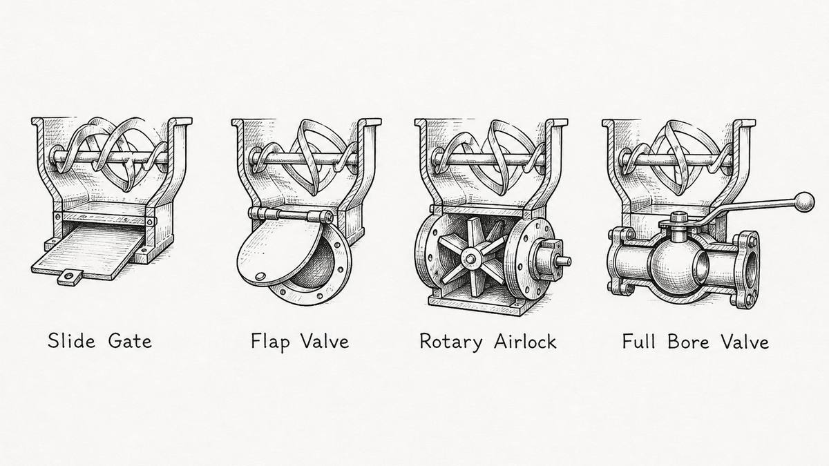
- Slide gate
- A flat plate that slides across the opening. Cheapest, simplest, and workable for free-flowing granules. Its weakness is the sliding face itself: powder works into the gap, and the plate increasingly has to be forced. Good where the opening is large and the product is coarse.
- Flap valve
- A disc on a hinge that swings shut under the weight of the product and opens when it is pulled. It seals well against a light powder because the product itself helps close it. It does not meter anything, so on a blender that has to discharge at a controlled rate it is the wrong choice.
- Rotary airlock
- A cylindrical body with a multi-vane rotor that turns and drops the powder out in pockets. It meters well and it separates the blender from whatever is downstream, which matters if the next stage is under pressure or vacuum. Its weakness is the rotor tip clearance, which wears, and the shear it applies to fragile granules.
- Full bore valve
- A straight unobstructed bore through the body, opened by a plug or a disc. Nothing in the path to bridge over, nothing to wear in a sliding face, and it can be built to clean in place. The most expensive of the four, and the usual answer for a powder that bridges or for a hygienic line.
Two questions take the guesswork out of the choice. Does the powder bridge? A bridging powder needs an opening large enough that an arch cannot form across it, and the opening size is a figure to be written down, not left to the valve maker. Does the plant need to run the discharge at a set rate? If it does, the valve has to meter, and that removes the flap and the slide gate from the list.
The seat of the discharge valve is also a cleaning surface. A valve whose seat is a groove or a step creates exactly the kind of seam the food rule is written about, and a valve that cannot be taken off the trough cannot have its seat cleaned. On a hygienic machine the valve is usually built to be unclamped and lifted away in one piece.
What happens after the valve is a separate decision with its own cost, and it is worth settling it in the same enquiry rather than after the blender arrives. A powder that has to travel horizontally, or that has to be fed into another process at a steady rate, usually leaves through a screw conveyor matched to the blender's discharge rate. If the two are bought from different factories, the interface between them — the flange, the height and the opening size — is the part nobody owns.
The two shaft seals are the other half of this section, and they are the parts that leak. A sealing arrangement on a ribbon blender shaft has to run against a rotating surface, hold powder in, and stay cleanable. Three arrangements are common: a packed gland, which is simple and needs periodic tightening; a lip or mechanical seal, which seals better and is less tolerant of a worn shaft; and a purge arrangement that blows clean air or gas outward through the seal so that powder never reaches the sealing faces. The purge version is the one that solves the pharmaceutical problem of a lubricated bearing near the product, and it is also the one that needs a supply of clean gas the plant has to have thought about. Whichever is chosen, the question to ask is the same: what does the shaft surface look like where the seal runs, and what happens when it wears a groove there.
Adding Liquid Without Making Lumps
Many blends are not two powders but a powder and a small amount of liquid — a flavour, a colour, a binder, a fat, a little water. A ribbon blender can do that job well, and it can also turn the whole batch into a sticky mass, and the difference is almost entirely about how the liquid arrives.
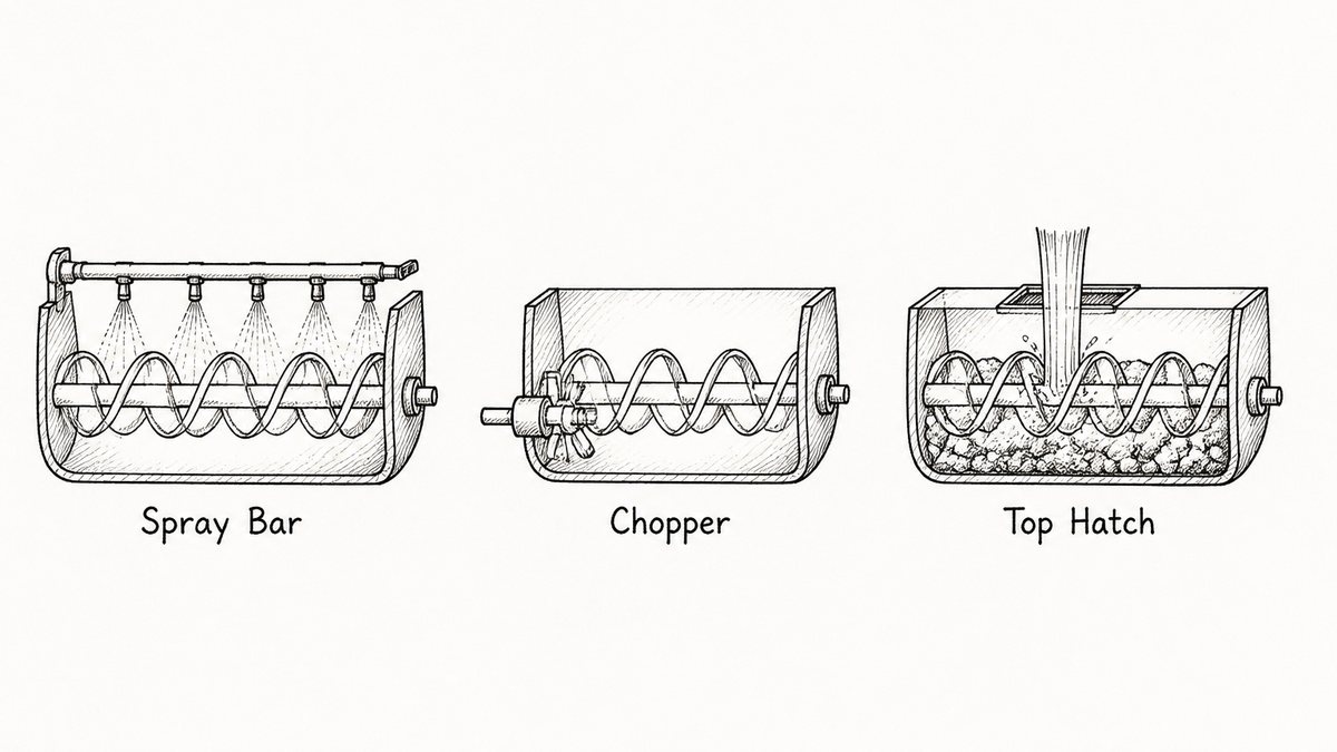
The spray bar is the default answer and the right one in most cases. A pipe across the width of the trough, above the ribbons, carrying a row of nozzles that produce a fine cone. The liquid meets falling powder, and the powder that is already moving carries it away before it can collect anywhere. The details to fix are the number and spacing of the nozzles, the spray pattern, and the pressure the plant can actually supply, because a nozzle rated at a higher pressure than the plant has will dribble instead of spray, and a dribble is how lumps start.
The chopper is the answer when the liquid is thick or when it has to be worked in. A small high-speed shaft with short blades entering the trough through the side wall low down. It breaks up the agglomerates the ribbons cannot, and it does it in the zone where the material is densest. It is a separate drive, a separate set of rotating seals and a separate cleaning item, so it is not something to add for convenience. It is the right addition when the product needs it, and it should be specified with its own blade form and speed range rather than as the word chopper.
Pouring through the top hatch is the mistake. It is also the way most plants describe the job when they order their first blender, because it is what they do by hand. Liquid arriving at one point, through a static layer, soaks into a small volume of powder and makes a dense mass that the ribbons push around intact. The mass gets coated by dry powder, looks blended from above, and turns up later as a lump in a finished product or at a filling head.
The order of addition matters as much as the hardware, and it is worth writing down. Powder first, then start the ribbons, then spray into moving powder, then keep the ribbons running for the agreed blend time after the spray stops. Liquid added before the ribbons turn, or at the end when the machine is slowing down, produces the same lumps the top hatch produces. A supplier who quotes a spray bar but says nothing about the addition sequence has supplied half the answer.
The liquid itself is usually dosed from a separate piece of equipment and that is where the accuracy of the blend comes from. A peristaltic or progressive cavity pump gives a repeatable volume against a pressure the ribbon blender cannot influence, and a screw pump chosen for a steady flow at low pressure is the usual choice for a thick additive. If the dosing is done by hand from a jug, the blend is only as repeatable as the person holding the jug, and no amount of mixing time will fix that.
Proving the Blend: the Thief, the Samples and the Number
Sooner or later a plant has to show that a blend is uniform, and this is the part of the subject where the most confident claims rest on the least evidence. A uniformity figure is not a property of the machine. It is the result of a sampling exercise, and it means nothing unless the exercise is described alongside it.
Four things have to be settled before a uniformity figure can be interpreted.
- Where the samples were taken from
- A thief pushed down through the powder in several places, in a pattern that covers the trough. Samples taken only from the top surface, or only from near the discharge, describe those places and no others. The interesting places are the ones a blend fails at: against the wall the ribbon does not reach, in the corners at the trough ends, and directly above the discharge opening.
- How many samples
- One sample establishes nothing about uniformity, because uniformity is a statement about the differences between places. A blend needs enough points to show those differences, which on a full trough means a grid rather than a handful.
- What the sample is analysed for
- The component that decides acceptance — an active, a colour, a marker or a critical minor ingredient — and the method used to measure it. Two plants can analyse the same samples by different methods and reach different conclusions, so the method belongs in the record.
- How long the machine ran before sampling
- The blend time, and whether it was measured from a cold start or from an already moving machine. A time quoted without that context is not comparable with anything.
The number itself is usually expressed as a percentage spread around the mean, and the common shorthand is a low value meaning a tight blend. That is the whole of what the figure says. It does not say how long the blend will take in a different batch size, and it does not survive a change of product — a machine that blends two similar free-flowing powders tightly can fail badly on a pair where one is three times denser than the other, because the ribbons move volume rather than mass.
What a buyer can do about all of this before ordering is small but effective, and it costs nothing.
- Ask for the sampling plan in writing, not just the result. How many points, where they were taken, and how long the machine ran. If the factory cannot produce that, the figure was marketing.
- Ask for the test to be run on a representative blend, not on sand. A factory test on a free-flowing demonstration powder tells you the machine turns. A test on the actual two components, at the actual ratio, tells you something about the blend.
- Make the first production blend a documented trial. The blend time that comes out of it becomes the plant's own number, and it should be recorded with the batch, the fill level and the components, so that the next person can compare.
The piece of hardware that makes this practical is unglamorous and is worth specifying: a sample thief long enough to reach the bottom of the trough at the deepest point, and sample ports positioned so that a person can take points across the whole length rather than only where they can reach over the lid. A trough that cannot be sampled properly cannot be proven, and no instrument panel changes that.
How These Machines Actually Fail
A ribbon blender has no bearings inside the product zone, no high-speed rotor and no complex geometry. That is why it lasts. It fails in four predictable ways, and all four are visible before the machine is packed.
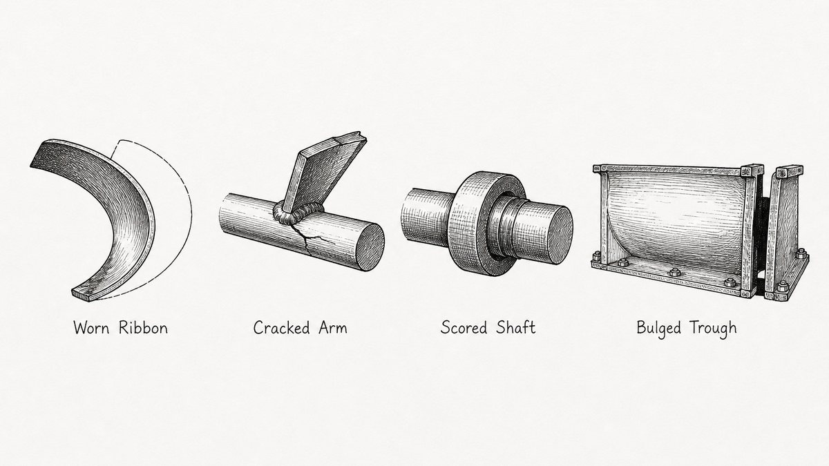
- Worn ribbon
- The outer edge of the outer ribbon is the part that does the work nearest the wall, and on an abrasive powder it wears into a thin, bright edge. As it wears, the clearance to the wall grows, and the machine quietly stops sweeping the wall. Nothing alarms, and the blend simply gets worse over months. The cause is either an abrasive product with no wear allowance, or a ribbon made from a thinner section than the duty needed.
- Cracked arm
- The short radial arms that join ribbon to shaft carry the whole load, and they are welded on. A fatigue crack at an arm weld starts at the toe of the weld, usually because the weld was made without a smooth transition, or because the drive starts under a full load and the arm is loaded in a direction it was not designed for. This is a build fault, and it is the one that turns into a machine-destroying failure when the arm lets go.
- Scored shaft
- Where the shaft runs through a packed gland, a hard or gritty powder works into the packing and polishes a groove into the shaft. Once the groove is deep enough, no amount of packing will seal it, because the seal is now running on a stepped surface. The cure is a shaft sleeve, which is cheap when it is designed in and expensive when it is not.
- Bulged trough
- The side of the trough bows outward under a dense powder at full fill, and the gap at the discharge opening opens up. The powder then leaks past the valve while the machine is closed, or the discharge stops sealing at all. This is a stiffness problem rather than a strength problem: it comes from plate that is too thin or from stiffening that was left off the drawing, and it is worst on a machine bought by total volume and run heavier than the shell was designed for.
Two of those four come from the product and two come from the build, and the two that come from the build are the ones worth checking before shipment, because both are measurable in the factory. The ribbon-to-wall clearance can be measured at several points along the trough. The arm welds can be inspected and their profile seen. The trough can be checked for flatness along its length and the shaft checked for straightness. The shaft surface where the seal runs can be measured and its hardness checked. And the discharge opening can be measured against the drawing, because an opening that is a few millimetres small will bridge where the design opening would not.
That is the case for treating this machine like every other piece of plant equipment in the category and putting a pre-shipment inspection with measured dimensions on the record in front of the shipping date. On a blender, the measurements that matter are few and all of them are taken with a tape, a feeler gauge and a straight edge rather than with instruments. That makes a measured record cheap to obtain and unusually useful, because the numbers go into the maintenance file and become the baseline for every wear check the plant does afterwards.
There is a second reason to check the first machine carefully rather than the tenth. A trough is rolled, formed and welded, and the first one out of a new set of rolls is where the tooling error shows. That is the argument for a first article inspection on the trough and ribbon set before the run continues: check the clearance, the pitch, the arm weld profile and the discharge opening on unit one, and the rest of the order follows the same tooling.
What to Send, and What to Check in the Quotation
An enquiry that goes out as a volume and a kilowatt comes back as a price for a box. One that goes out in four blocks comes back as something that can be compared with the next quotation. These are the four blocks, and each one exists because a factory cannot size the machine without it.
Ten Lines a Ribbon Blender Enquiry Has to Carry
| What to send | Why the factory cannot answer without it |
|---|---|
| The components by name, with bulk density for each and the ratio between them | Bulk density sets the trough volume and the drive load, and a large density difference is what makes a blend hard rather than the number of components |
| Working volume required, with the fill level you intend to run at | Total volume and working volume differ by a large margin, and the fill level decides the ribbon geometry |
| Whether anything is added as a liquid, what it is, how much and how fast | A liquid addition turns a two-powder blender into a machine with a spray system, a chopper question and an addition sequence |
| Blend time required, and the uniformity figure the plant has to meet | Both are acceptance criteria, and neither can be designed against if the sampling plan behind the figure is unknown |
| Trough material and minimum plate thickness after forming | Thickness is what stops the trough bulging at full fill, and forming thins the plate |
| Ribbon-to-wall clearance and ribbon pitch as figures | These two numbers decide whether the wall is swept and how long the blend takes; as adjectives they mean nothing |
| Surface finish for each food-contact surface, written surface by surface | The trough bore is easy to polish; the end-plate weld, the underside of the shaft and the discharge seat are not |
| Discharge valve type, with the opening size and whether it has to meter | Bridging is prevented by opening size, and metering removes two of the four valve types from the list |
| The seal arrangement at both ends, and what happens when the shaft wears | A packed gland wears the shaft; a removable sleeve or cartridge is designed in or not at all |
| Which items are inside the scope: drive, seals, spray bar, chopper, controls, sample ports | These are the lines that move between quotations, and they are the reason two prices for the same machine differ by half |
Reading the answers back is quicker than it looks. Check that the working volume comes with the bulk density it was calculated on, and that the density is the one you measured rather than a typical figure. Check that the clearance and pitch are given as numbers. Check that the surface finish appears more than once, because a single figure usually applies only to the trough bore. Check the list of items excluded from the scope, because that list is where the money is. And check that the blend time has a fill level and a product attached to it, because a blend time on its own is the least useful number in the document.
The last step is the one that carries all of it into the factory. What comes back from the enquiry is a quotation; what the factory needs to build from is a signed sheet with a revision number on it, which is why it is worth writing the result up as a product specification sheet the factory signs and works to rather than leaving the details spread across an email thread.
How much does a ribbon blender cost?
There is no useful average, because the price follows the working volume, the ribbon set, the trough material and how much of the equipment is bought rather than made. Two machines listed at the same size can differ by a multiple if one is carbon steel with a packed gland and a slide gate and the other is polished stainless with a removable seal cartridge, a full bore discharge and a spray system. What a buyer can do is ask for the price broken down by block: the trough, the ribbon set and drive, the discharge, the seals, and the controls and instruments. That turns the total into something comparable. The items that move the number most are the plate thickness and material, the drive make and frame size, the surface finish specification, the seal arrangement, and whether the spray system, chopper and sample ports are inside the scope at all.
What is the difference between a ribbon blender and a paddle mixer?
A ribbon blender moves material around the trough with two counter-wound ribbons, which makes it gentle and good at blending large volumes of similar powders. A paddle or plough mixer turns a shaft carrying shaped blades or ploughs at higher speed, which throws the material into the air inside the vessel and gives a much more intense mix. That intensity is what you want when the components differ a lot in density or when a liquid has to be worked in hard. It is also what you do not want with a fragile granule, because the high speed breaks it. A ribbon blender is usually the better choice for a simple two-powder blend in a large batch; a paddle or plough mixer is usually the better choice when the blend is difficult, the batch is small, or the machine also has to do some size reduction.
What is the working volume, and how full can I run it?
Working volume is what the trough holds when it is filled to the level the ribbons can actually work with, and it is normally somewhere between half and three quarters of the total volume printed on the drawing. The exact fraction depends on the powder rather than on the machine: a light free-flowing powder can be run higher, a dense or poor-flowing powder lower, because the ribbons have to be able to lift material off the top of the heap. The number that decides it is the bulk density, so the working volume and the density belong together on the enquiry. A machine bought on total volume and run at that volume will be overloaded, and the first sign is usually a drive that trips on start-up.
Can a ribbon blender handle a liquid?
Yes, in small amounts, and the amount is the whole question. A ribbon blender can add a few percent of liquid by weight — a flavour, a colour, a binder, a little fat or water — and distribute it well if it is sprayed onto powder that is already moving. What it cannot do is wet a powder out to a paste. As the liquid fraction rises, the material stops behaving like a powder and starts behaving like a mass, the ribbons push it around instead of mixing it, and the load on the drive climbs sharply. If the process needs more than a small addition, the machine is wrong for the job and the answer is a different mixer, not a longer blend time.
How long does a blend take?
It depends on the ribbon pitch, the working volume, the blend time required and how different the components are, so any single figure is only meaningful with those attached. As a rough guide, a simple two-powder blend in a normally filled trough reaches a good mix in a few minutes, and a blend where one component is much denser than the other takes considerably longer. The trap is that a longer time does not always help: past a certain point the blend is as mixed as the machine can make it, and more running only adds heat, wear and dust. The way to find the right number is to sample at intervals during a trial and stop when the samples stop improving, then write that time down as the plant's own figure.
What should I check before the machine ships?
Five measurements and one look. Measure the ribbon-to-wall clearance at several points along the trough, because that is the number that decides whether the wall gets swept. Measure the ribbon pitch against the drawing. Check the trough for flatness along its length and the shaft for straightness before anything is packed. Measure the discharge opening, because an opening a few millimetres small will bridge. Measure the shaft surface where the seal runs, and note its condition so you have a baseline for wear. Then look at the arm welds, and look at the weld where the trough meets the end plate, because that is a food-contact seam and it should be continuous and ground rather than tacked. All of these are tape and feeler gauge checks, which is why a measured record is cheap to obtain on this machine and unusually useful later.
Send the densities and the fill level — the volume alone is not enough
Tell us what has to be blended and what the plant has to prove. The two components with their bulk densities, the working volume you need, whether anything is added as a liquid, and the blend time the plant has to meet. Then the trough, the ribbons, the seals and the discharge.
Request a Ribbon Blender Sourcing Quote
Questions & Comments
We read every one and reply within 24 hoursMost blender arguments come down to two figures that were never written down: the working volume and the bulk density it was calculated on, and the clearances the ribbons run at. Send us both, and we will pin them down before the order.