
Design for Manufacturing (DFM) Review: How to Optimize Product CAD Before Tooling (2026 Guide)
 ·
Updated October 1, 2026
·
20 min read
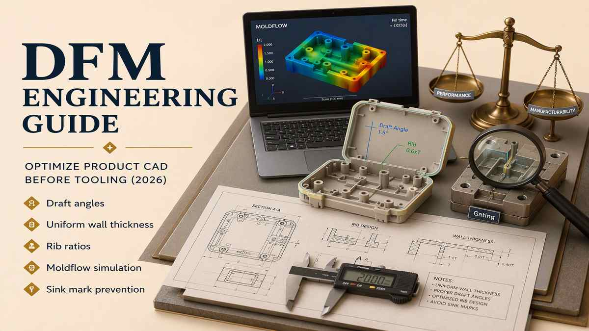
Direct Answer: A professional Design for Manufacturing (DFM) Review is the most critical engineering gate between your 3D CAD concept and cutting hardened steel injection molds in China. In 2026, executing a strict DFM review eliminates 90% of all injection molding defects before spending a single dollar on tooling. The DFM Golden Checklist requires checking 7 core mechanical pillars: (1) Draft Angles (≥1.0°–1.5° on vertical faces + 1.0° extra per 0.025 mm of Mold-Tech texture depth to prevent scuff marks); (2) Uniform Wall Thickness (constant 2.0–3.0 mm base wall with 3:1 transition ramps to eliminate warpage); (3) Rib Thickness Ratio (ribs designed at 40% to 60% of base wall thickness with R0.5 mm fillets to prevent front-face sink marks); (4) Undercut Elimination (using core shutoffs to remove \$1,500 mechanical sliders); (5) Parting Line Concealment; (6) Autodesk Moldflow Gating & Weld Line Simulation; and (7) Perimeter Air Venting (0.02–0.04 mm) to prevent burn marks. Catching design flaws in CAD costs \$0; fixing them after cutting S136 steel costs \$5,000+ and months of delay.
Industrial designers create beautiful 3D renderings in Rhino and SolidWorks, focusing on aesthetics, ergonomics, and branding. However, what looks stunning on a 4K computer monitor can become a manufacturing nightmare when molten 230°C plastic resin is injected under 150 tons of hydraulic pressure.
Without a comprehensive DFM review, founders discover disastrous defects on their first T1 mold trial: severe cosmetic sink marks opposite internal screw bosses, warped enclosures that will not snap together, visible weld lines running across the brand logo, or parts that lock inside the mold cavity due to zero draft angles.
In this comprehensive 2026 engineering guide, we break down the 7 common plastic defects and their DFM CAD solutions, decode the core DFM rules for draft angles, walls, and ribs, explain how to interpret Autodesk Moldflow simulation reports, expose 3 red flags in factory DFM reviews, and share a 5-step SOP to optimize your product CAD before authorizing steel cutting in China.
7 Common Plastic Molding Defects & DFM CAD Solutions
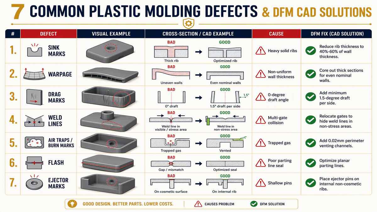
To understand why DFM is essential, examine how specific 3D CAD design choices cause or prevent common injection molding flaws:
| Molding Defect | Root Engineering Cause | DFM 3D CAD Solution |
|---|---|---|
| 1. Sink Marks (表面缩水凹痕) | Heavy solid plastic sections and overly thick internal ribs/bosses cool slowly and pull inward. | Core out thick sections; restrict rib thickness to 40%–60% of base wall thickness. |
| 2. Warpage & Bowing (产品翘曲变形) | Non-uniform wall thickness causes differential volumetric cooling and internal stress. | Enforce uniform even wall thickness; add structural diagonal cross-ribs. |
| 3. Drag / Scuff Marks (脱模拉伤刮花) | Zero or not enough draft angle on vertical walls causes heavy friction during mold ejection. | Add minimum 1.5° draft per side (+1.0° per 0.025 mm of texture depth). |
| 4. Weld / Knit Lines (熔接线痕迹) | Two converging molten plastic flow fronts collide and cool around holes and core pins. | Relocate injection gates; increase wall thickness locally to promote flow fusion. |
| 5. Air Traps & Burns (困气烧焦痕) | Trapped air cannot escape rapidly during fast injection, compressing and burning resin. | Design 0.02 mm to 0.04 mm parting line vent channels at end-of-fill zones. |
| 6. Parting Line Flash (合模线披锋毛边) | Complex 3D stepped parting lines flex under high injection clamping pressure. | Simplify parting lines into flat 2D planar shut-off faces. |
| 7. Ejector Pin Stress Marks (顶白破裂) | Small ejector pins push against thin cosmetic walls before plastic is fully rigid. | Place larger ejector pins directly on internal structural ribs and screw boss bases. |
Core DFM Rules: Draft Angles, Uniform Wall Thickness & Rib Ratios
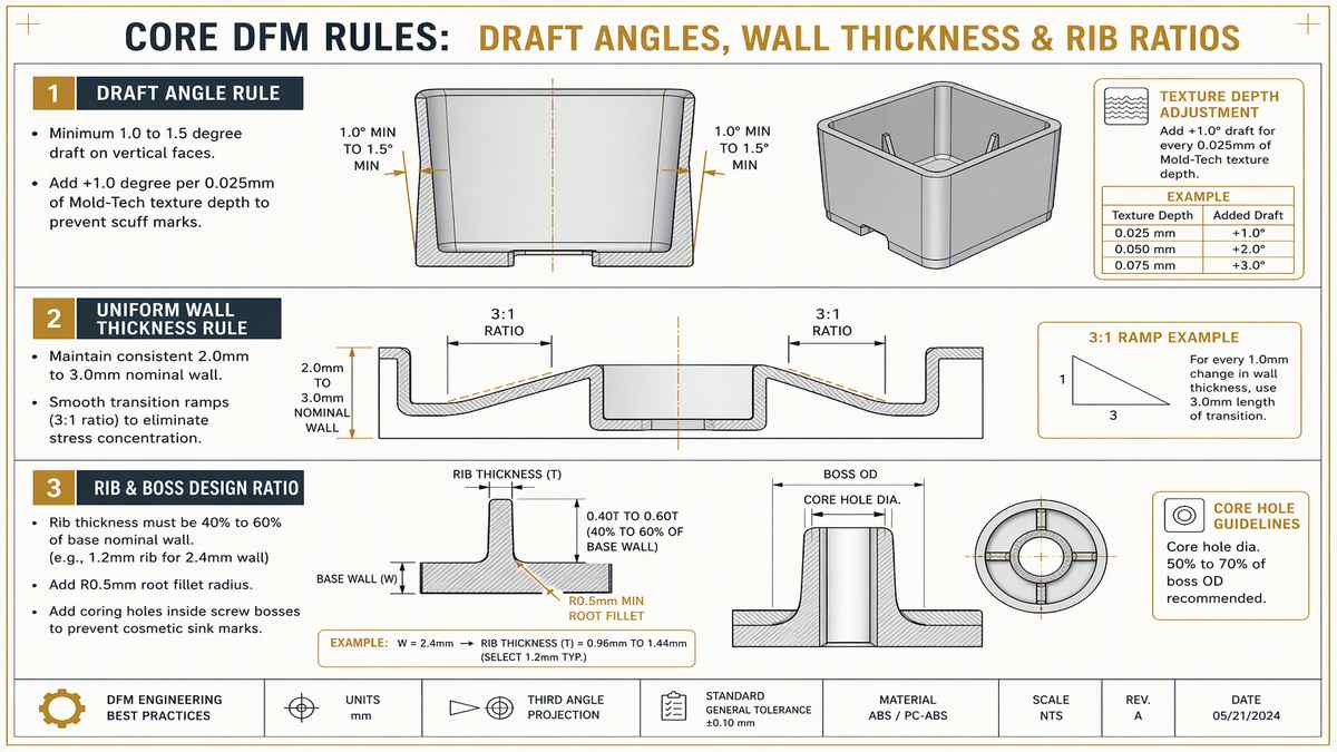
To ensure smooth toolmaking under Plastics Industry Association SPI Mold Standards, enforce these three non-negotiable geometric rules:
Anatomy of a Moldflow Simulation Report: Fill, Weld Lines & Warpage
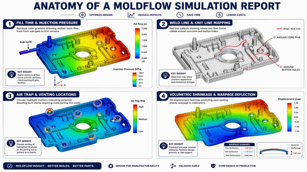
Before releasing 3D CAD to the CNC toolroom, leading toolmakers run finite element filling simulations using Autodesk Moldflow Simulation Software. Here is what to inspect:
3 Red Flags in Fake Factory DFM Reports
Low-cost Chinese mold shops often send superficial “rubber-stamp” DFM reports. Watch out for these three warning signs:
5-Step SOP for Hardware DFM Review & CAD Optimization Before Tooling
Follow this standard operating procedure to optimize your 3D CAD models before cutting production steel:
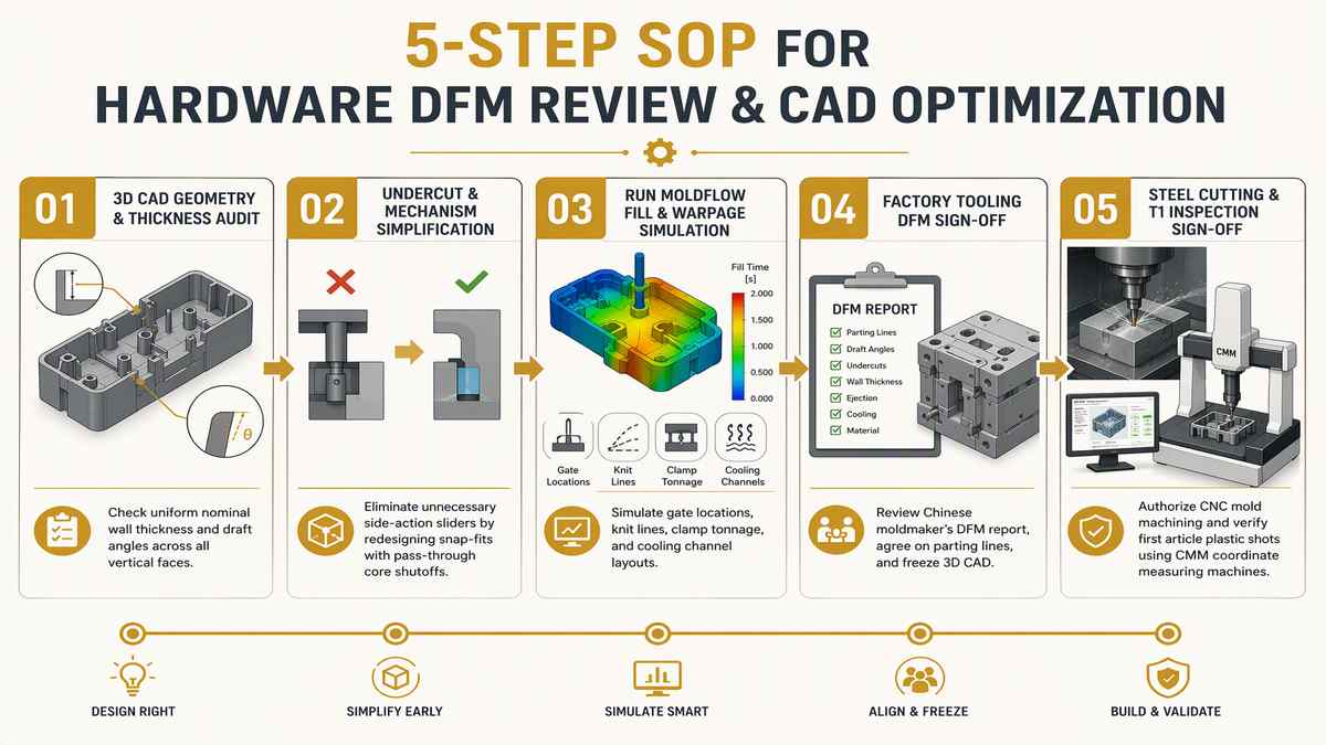
- Execute 3D CAD Geometry & Wall Thickness Audit: Run cross-sectional thickness analyses in CAD to check uniform 2.0–2.5 mm base walls, apply ≥1.5° draft angles to all vertical core/cavity faces, and apply 50% rib thickness rules.
- Simplify Undercuts & Eliminate Costly Sliders: Redesign internal snap-fit hooks with pass-through core shutoff holes to allow simple 2-plate mold opening, saving \$1,000 to \$2,000 per eliminated slider mechanism.
- Run Complete Moldflow Filling & Warpage Simulation: Simulate gate locations, optimize sub-gate vs. hot runner nozzles, check clamp tonnage requirements, and analyze cooling water circuit efficiency under ISO 9001 Quality Management Standards using our China factory audit checklist review.
- Sign Enforceable Bilingual Tooling Contract & Freeze DFM: Lock parting line locations, gate vestige standards, and mold steel grades (P20, NAK80, S136) into an enforceable bilingual manufacturing sales contract under PRC law, applying insights from our guide on prototype tooling vs production tooling strategies.
- Inspect T1 Trial Plastic Shots with FAI Sign-off: Order 20 to 50 initial T1 plastic test parts and execute a comprehensive first article inspection (FAI) sample review with Coordinate Measuring Machines (CMM) before performing a pre-shipment inspection (PSI) in China.
Illustrative Scenario: How a San Francisco Brand Saved \$22,000 via DFM
To see how professional DFM review prevents catastrophic tooling failures, review this consumer electronics enclosure case study:
A consumer electronics startup in San Francisco, California developed a slim magnetic wireless power bank enclosure (Flame-retardant PC/ABS, 50,000 annual production volume, \$150,000 finished goods value).
- The Unoptimized CAD Disaster: The founder’s original 3D CAD design featured 0° draft on exterior sidewalls, heavy 4.5 mm thick solid internal screw bosses (adjacent to a 2.2 mm base wall), and zero radius fillets. An initial sample mold produced in Shenzhen yielded parts with severe cosmetic sink marks on the front face and heavy scuff scratches upon ejection.
- The Sourcing Pioneer DFM Intervention: Sourcing Pioneer conducted an exhaustive DFM overhaul: (1) Added 1.5° draft angles to all vertical casing walls, (2) Cored out the solid screw bosses with R0.6 mm base fillets to maintain uniform 2.2 mm wall thickness, (3) Reduced rib thickness to 1.1 mm (50% ratio), and (4) Repositioned the gate to a sub-surface tunnel gate to hide cosmetic vestige marks.
- Flawless T1 Trial Sign-off: The revised S136 steel mold produced T1 sample parts with 100% zero sink marks, smooth ejection, and ±0.03 mm snap-fit alignment.
- The Commercial Outcome: The DFM optimization saved the startup \$22,000 in mold rebuilding costs, reduced injection cycle times from 28s to 19s (saving \$14,000 in part piece costs), and enabled an on-time Kickstarter fulfillment with a 4.9-star backer rating.
Frequently Asked Questions (FAQ)
What is a DFM review in plastic injection molding?
A DFM (Design for Manufacturing) review is an engineering evaluation of your 3D CAD model conducted before cutting steel tooling. It analyzes draft angles, wall thickness uniformity, rib ratios, parting lines, gate locations, and Moldflow fill simulations to eliminate plastic defects like sink marks, warpage, and drag scratches.
What is the golden rule for internal rib thickness to prevent sink marks?
To prevent cosmetic sink marks on the front exterior surface, internal structural ribs and screw boss walls must be designed at 40% to 60% of the adjacent base wall thickness (e.g., for a 2.4 mm base wall, rib thickness should be 1.0 mm to 1.4 mm max) with R0.5 mm root fillets.
How much draft angle is required for textured plastic injection parts?
Standard smooth vertical faces require a minimum of 1.0 to 1.5 degrees of draft angle per side. If the plastic surface has Mold-Tech EDM texture or leather graining, you must add an extra 1.0 degree of draft for every 0.025 mm (0.001 inch) of texture depth to prevent scuff marks during mold opening.
How does Moldflow simulation software help hardware startups save money?
Autodesk Moldflow simulates the molten plastic fill front, injection pressure, clamp tonnage, weld line locations, and post-cooling warpage inside a virtual mold. This allows engineers to optimize gate placement and cooling channels before cutting steel, preventing $10,000+ mold rebuilding costs.
How can designers eliminate expensive side-action sliders in injection molds?
Designers can eliminate mechanical side-action sliders by adding through-hole cutouts (core shutoffs) directly beneath snap-fit latches or side clips in the 3D CAD model. This allows the core and cavity steel to form the undercut feature in a simple 2-plate opening mold, saving $1,000 to $2,000 per slider.
Optimize Your 3D CAD Before Cutting Steel to Prevent Costly Tooling Flaws
Our China tooling engineering team runs professional Autodesk Moldflow simulations, audits draft angles and rib ratios, and identifies critical molding flaws before you pay mold deposits.
Get Free CAD DFM Tooling Review
Questions & Comments
We read every one and reply within 24 hoursReviewing a 3D CAD design for injection molding, wondering about draft angle calculation for textured surfaces, or need Moldflow simulation and DFM review in China? Post your CAD and tooling questions below — our on-the-ground manufacturing engineers will guide your engineering optimization.