
Gear Motor Manufacturer: Sourcing Geared Motors and Gearboxes From China
 ·
Updated October 12, 2026
·
26 min read
A gear motor — also called a geared motor or a gear reducer — is an electric motor bolted to a gearbox so that the pair turns slowly and pulls hard. Buyers quote it on two numbers, power and ratio, and then argue about price; the two things that actually decide whether the pair is still running in three years are the duty cycle and the oil. There is a third thing almost nobody opens, and it is federal: the motor inside a gearmotor is covered by the energy rules in Title 10 of the Code of Federal Regulations, those rules say they reach a motor made “alone or as a component of another piece of equipment”, and the same section takes motors out again when they are built for one particular job. Which side of that line your gearmotor sits on decides what your supplier has to hand over with the crate.
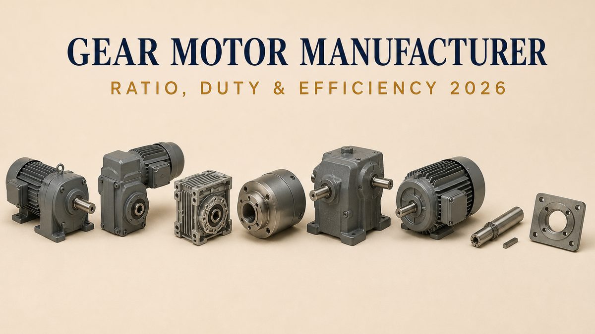
Six Lines That Decide Whether a Gearmotor Order Is Complete
| What the buyer has to settle | Why it is not obvious | The line on your order that closes it |
|---|---|---|
| Output speed and torque, not just power | A motor of a given power can be built to almost any output speed, and torque rises as speed falls | Output rpm and output torque, with the ratio that produces them |
| Duty cycle and starts per hour | A gearbox that is fine on a fan is too small on a machine that starts and stops all day | The hours a day it runs, and how often it starts, in writing |
| The mounting, exactly | Foot, flange, hollow shaft and torque arm load the bearings and the shaft in different ways | The mounting type plus the shaft centre height or the flange bolt circle |
| The motor that is inside | The motor has its own rules, its own data plate and its own efficiency standard | Power, voltage, phase, frequency, poles, enclosure and insulation class |
| Who keeps the oil out and who lets it out | Mounting position decides where the oil sits, and a breather and a seal decide whether it stays | The mounting position, the oil grade and the seal arrangement |
| The shaft end the machine will see | An exposed shaft and an unused keyway are the first thing a safety inspector looks at | Keyed or plain, keyway size, and a cap or sleeve on the free end |
What a Gear Motor Is, and the Words Around It
The part is simple to describe and surprisingly hard to order. A gear motor is one electric motor and one gearbox, joined so that they share a job: the motor supplies the turning effort at high speed, and the gearbox trades most of that speed away in return for more turning effort at the output shaft. Nothing about the pair is free, and nothing about it is separate. Six words carry the whole subject.
- Gear motor, geared motor, gear reducer
- Three names for the same thing, and the trade uses them without much discipline. A gear motor or a geared motor is the complete unit: motor plus gearbox, tested together and sold together. A gear reducer or a gearbox is the toothed part on its own, sold to somebody who already has a motor and a coupling. This matters when you ask for a price, because a factory that builds reducers will happily quote you a gearmotor by adding a bought-in motor and a markup, and the number will look perfectly normal.
- Ratio
- The number of turns the motor shaft makes for one turn of the output shaft. A ratio of sixty to one means the motor turns sixty times while the output turns once. The ratio comes from counting teeth: divide the teeth on a driven wheel by the teeth on the wheel that drives it, multiply that out across every stage in the train, and you have the ratio. It is a count, not a measurement, which is why a factory can tell you the ratio exactly and still get the output speed wrong on a fifty-hertz supply.
- Torque
- The turning effort at the output shaft, measured in newton metres or in pound-inches. It is what actually lifts the load or drives the screw, and it is the number that should be on your order instead of motor power. Torque and speed are tied together by the power, so at any given power, a gearbox that halves the output speed doubles the output torque — and that is the entire commercial argument for buying a gearbox instead of a bigger motor.
- Service factor
- A multiplier a gearbox maker puts on a rating to allow for the fact that real machines shock and shake. A gearbox chosen at exactly the running torque will be overloaded every time the machine starts or jams. Buyers who have never heard the term still feel its effect, and it always shows up as the same sentence: the gearbox is rated at what the load needs, and the load is not steady.
- Duty cycle
- How the machine runs over a day: continuously, in bursts, or start-stop with a pause between. It is a heavier burden than the load, because heat builds up in the motor and the oil during every start and cannot escape during a stop. Two machines with identical loads and different duty cycles need different gearmotors, and the one that needs more is the one that stops and starts.
- Rated load
- The nameplate figure the motor is rated at, and here the federal rule is unusually blunt and unusually useful. It defines rated load as “the rated output power of an electric motor”. Output, not input. The power the motor takes from the wall is always higher than the power it puts on its shaft, and the difference is heat. A buyer who quotes a gearmotor on input power is quoting a bigger number than the part will deliver.
One boundary line is worth drawing at the very start, because it changes who you buy from and what you can expect in writing. A gearbox factory cuts gear teeth. It buys bearing steel, cuts and grinds teeth to a controlled profile, machines a housing, and knows more about tooth contact and oil than any motor maker ever will. A motor factory winds copper and stacks laminations, and knows more about magnetic steel, slot fill and heat than any gear cutter. A gearmotor needs both, and there are three different kinds of supplier: a gearbox works that also buys and fits motors, an electrical works that also buys and fits gearboxes, and the many assemblers who buy both and put them together. None of the three is dishonest. What matters is which one is answering your technical questions, because the answer to a gear question from a motor house is usually a plausible guess.
The Six Families, and What Each One Is For
The trade quotes about six families of gearbox, and they are not interchangeable in price or in character. They are told apart by the direction the output turns and by the shape of the teeth inside, and each family has one thing it does better than the others.
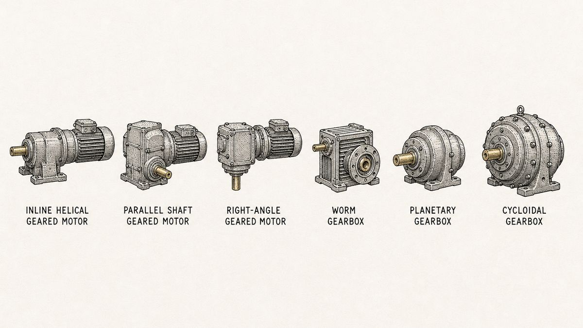
Inline helical. The gear teeth are cut at an angle to the shaft, which makes the mesh quiet and lets several pairs run in a row inside one slim housing. The output shaft is in line with the motor shaft, so the unit is long and narrow. This is the family for conveyors, mixers and anything running for hours a day, because helical teeth share the load across more than one tooth at a time and wear slowly. The price is that the housing has to be long, so it is the wrong choice when the machine is short of space.
Parallel shaft. Also helical teeth, but the output shaft is offset below the motor shaft and parallel to it, and the whole unit is lower and squarer than an inline. It is the everyday industrial gearbox behind belt conveyors, agitators and screw feeders, and it is usually the cheapest way to get a large ratio in a compact shape. The offset is the thing to check on the drawing, because it decides how high the machine's drive shaft will sit.
Right-angle. A set of bevel or hypoid gears turns the drive through ninety degrees, so the output shaft comes out square to the motor. That saves length on a machine and it is why right-angle units dominate on mixers, on screw conveyors and on anything with a motor sticking sideways out of a tank. The cost is a second gear mesh to build, and with it a second place for noise and wear to come from.
Worm. A single-threaded screw shaft drives a large wheel whose teeth are cut at an angle, and the two shafts cross at right angles without touching. It gives a large ratio from one single pair of parts, it is quiet, and it usually holds itself still when the motor stops, which is worth real money on a hoist or a gate. The trade is heat and loss: the sliding action between a worm and its wheel wastes energy and makes heat, so a worm gearbox is a poor choice for a machine that runs all day at speed.
Planetary. Several small gears orbit around a central sun gear inside a ring. The load is shared between three or four teeth at once instead of one, so a planetary unit is short, light and strong in a way no other family manages. It is the standard answer for servo applications, for anything that has to reverse often, and for anything where the gearbox itself has to be small. It is also the family where the price gap between a good unit and a cheap one is widest, because the tolerances and the bearings are what you are buying and neither is visible.
Cycloidal. A disc with a wavy rim wobbles inside a ring of pins, giving a very large ratio in a short, wide housing with almost no sliding contact. Shaft-mounted cycloidal units are common on heavy conveyors and on anything that takes a shock every cycle, and they tolerate a bad start better than most. The output is eccentric by design, so the wobble has to be taken out inside the unit, which is why the housing is wide and round.
Two rules come out of the list and they are worth more than the descriptions. Match the family to the duty before you compare prices, because a worm unit and a planetary unit that both claim the same ratio are not the same product and never will be. And ask which family a quotation is for, in writing. Quotations that name only a ratio and a power are quotations you cannot compare, and they are the ones that produce a crate of something the buyer never pictured.
Inside the Gearbox: the Parts, and Which One Actually Fails
The gear teeth are what the buyer thinks about and what the catalogue shows, and in real service they are rarely the part that ends the machine's life. The parts that fail are the ones that cannot be seen from outside: the oil, the seals and the bearings. A cut-away drawing is the only honest way to look at a gearmotor, so it is worth spending a paragraph on what is inside.
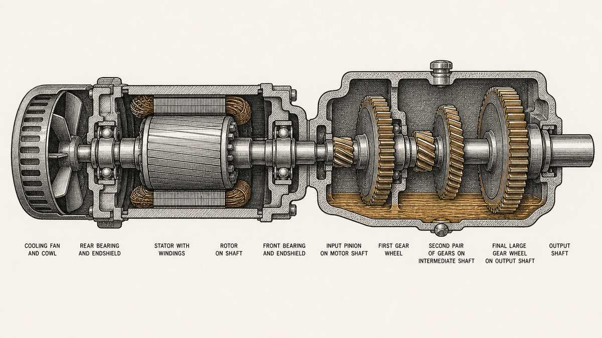
Follow the power from the left. The fan and its cowl pull air over the outside of the motor. Inside, the stator — the fixed part, carrying coils of copper in slots — makes a turning magnetic field, and the rotor, the part on the shaft, is dragged round with it. Two bearings, one at each end of the shaft, hold that shaft in line, and they sit in endshields that also close the motor against dust and water. The motor shaft then passes into the gearbox and carries the first small gear, called the pinion. The pinion drives a bigger wheel, that wheel may drive another pair on an intermediate shaft, and the last wheel is fixed to the output shaft, which leaves the housing through an oil seal and a bearing of its own.
Every one of those parts has a failure mode, and they are not equally likely.
The oil is the first thing to get right and the first thing to go wrong. It does three jobs at once: it carries heat away from the teeth, it keeps a film of lubricant between surfaces that slide, and it keeps rust off the inside of a cast iron housing. It also has to be in the right place, and that depends entirely on how the gearbox is mounted. Change the mounting and you have changed which parts are in the oil.
The seals are the second. The output shaft is the only part of a sealed gearbox that comes out through the housing, so it carries a lip seal that scrapes the oil back as the shaft turns. That seal is a wearing part. It sits on a surface that is also wearing, and a groove worn into the shaft under a seal is a classic way for a healthy gearbox to start marking its floor.
The bearings are the third, and they are where a bad choice of mounting shows up. Bearings carry two different loads at once: the weight of the gears and the shafts, and the pull of the driven machine. Mount the unit so its own weight hangs on the wrong bearing and you have quietly shortened its life. Mount it so the driven machine's pull is taken by a bearing that was sized for something else, and the same thing happens faster. Nothing about that shows in a price.
The teeth themselves are the fourth, and they fail in two ways that are easy to tell apart. A tooth can break — usually from a shock, a jam, or a foreign object arriving in the mesh — and that is a sudden, obvious death. Or a tooth can wear, slowly, until the profile is gone and the mesh is loose and noisy. Which of the two you get tells you what actually happened, and the two need different conversations with the supplier.
There is a practical lesson in the order of that list. On a machine that has just lost a gearmotor, the buyer's first question is usually about the gear steel, and the honest answer is usually about the oil and the mounting. A gearbox that failed with a black, sticky, burnt smell inside it has told you it was running hot, and heat comes from oil that is wrong, low, in the wrong place, or simply never changed. No steel grade fixes that.
Ratio, Speed and Torque: Three Numbers That Move Together
A gearmotor has one job on paper and one on the machine. On paper the job is to convert a fast, weak turn into a slow, strong one. On the machine the job is to do that at a speed the process actually needs, which is a different statement and is the one buyers get wrong. Ratio, output speed and output torque are bound to each other, and you cannot set two of them and let the third fall where it likes.
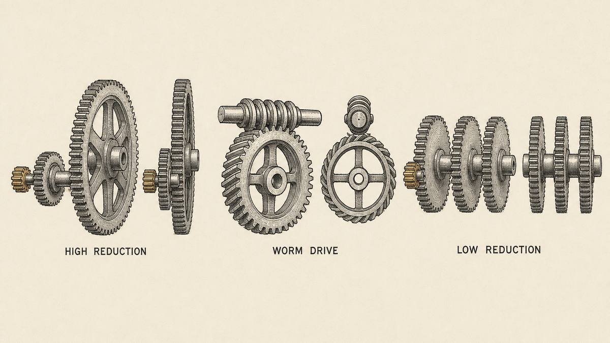
Start with the rule that governs everything else. Power is the product of torque and speed. Hold the power steady, as a motor does, and the two are locked in opposition: halve the speed and you double the torque, double the speed and you halve the torque. A gearbox is a device for trading one against the other, and it does the trading with teeth, so the trade is decided by counts rather than by measurements. That is why a gearbox maker can tell you the ratio with total confidence and still be wrong about the output speed of your machine.
The ratio is a count. Number of teeth on the driven wheel divided by number of teeth on the driving wheel gives the ratio of that one pair. Run two pairs in a row and multiply: a five-to-one pair feeding a six-to-one pair gives thirty to one. Nothing about the tooth size, the material or the price enters the arithmetic, and that is the point. When a factory quotes a ratio, it is repeating a count, and a count can always be checked from the drawing.
Output speed is a calculation, and it depends on the mains. Take the motor's speed, divide by the ratio, and you have the output speed — on the supply the motor was rated for. A four-pole induction motor runs at about 1,450 rpm on fifty hertz and about 1,750 rpm on sixty hertz, because the speed comes from the mains frequency and the number of poles, not from the motor's size. A gearmotor built and quoted for a fifty-hertz market and then run on sixty hertz will turn about twenty per cent faster than the catalogue says, draw more current, and produce less torque than the buyer expected at the shaft. This one paragraph has cost more buyers more money than any other in the subject, and it is entirely preventable: state the frequency and the voltage on the order, and ask the supplier to confirm the output speed at that frequency in writing.
Output torque is what the machine actually feels, and it is the number that should be on the order. Quoting a gearmotor on motor power alone is the commonest mistake in the whole trade, because the same motor power can be geared to a fast conveyor and to a slow mixer, and the two need completely different gearboxes. Two buyers order a one-and-a-half kilowatt gearmotor. One drives a screw feeder at thirty rpm and needs several hundred newton metres at the shaft; the other drives a fan at six hundred rpm and needs a twentieth of that. Same power, same price bracket, entirely different machine.
Three more figures belong beside the torque on any serious enquiry.
Starting torque and the shock that comes with it. A motor started direct on line can produce several times its running torque for the fraction of a second it takes to come up to speed, and a machine that jams can produce more than that. A gearbox sized at the running torque will take that overload in its teeth on every start. This is what a service factor is for, and it is why a quotation that names only a running torque has told you half of what you need.
Overhung load. If a pulley, a sprocket or a coupling is hung on the output shaft, that side pull is a load the gearbox has to carry in its bearings, and every gearbox maker publishes a limit for it. A buyer who fits a large sprocket on a small shaft because the shaft happens to have the right keyway has added a bending load nobody calculated. The pull grows with the diameter of the pulley, so a big pulley on a small gearbox is a worse idea than it looks.
Back-driving, and whether you want it. A worm gearbox usually will not turn backwards from the output, which means a raised load stays raised with the motor switched off. A helical or planetary unit will happily be back-driven, which means the same raised load will run down unless there is a brake. Neither behaviour is better; they suit different machines, and the time to decide is before the order, not after the first load has run away.
Put those together and the enquiry writes itself: output speed at the stated mains frequency, output torque at that speed, how the machine starts and whether it can jam, the side pull on the shaft if anything is hung on it, and whether the unit must hold its position when the power is off. A supplier who receives those five lines can quote a real gearbox. A supplier who receives a power figure and a ratio can only quote a shape.
The Motor Inside, and the Federal Rules That Come With It
The gearbox is the part buyers study. The motor is the part that carries the paperwork, and in the United States it is the part with a federal rule attached to it. That rule is worth twenty minutes of any gearmotor buyer's time, because it decides whether a supplier can sell you a certain motor at all, and because it gives you a way to ask a question that separates a factory from a trader in one sentence.
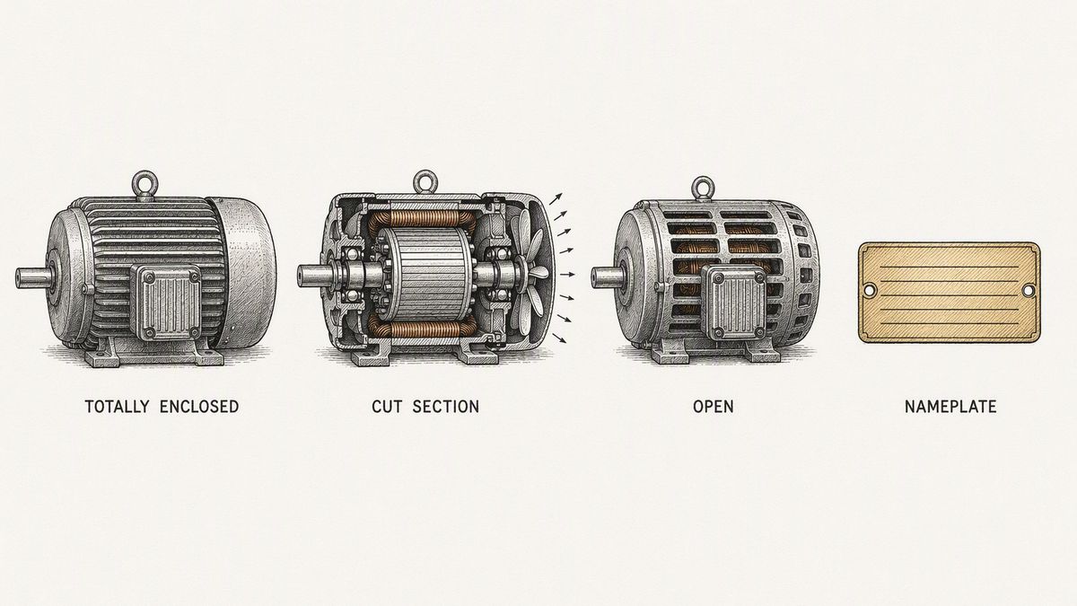
The rule lives in 10 CFR 431.12 for the definitions and 10 CFR 431.25 for the standards themselves. Both are free to read on the electronic Code of Federal Regulations, and both are short. Start with what the rule thinks a motor is, because the definition is broader than most people expect: an electric motor is “a machine that converts electrical power into rotational mechanical power”. That is the whole definition. It does not mention size, price, application or brand, which means a small motor inside a gearbox is a motor by this definition exactly as much as a large one standing on a foundation.
The sentence that catches a gearmotor is about where the motor ends up. The standards in 431.25 are written to apply to a motor manufactured “alone or as a component of another piece of equipment”. Read that plainly: a motor sold by itself is covered, and a motor built into a gearbox and shipped as a gearmotor is covered too. The efficiency standard follows the motor into the assembly. A supplier who tells you that the rules do not apply because he is selling a gear reducer, not a motor, has either not read the section or is hoping you have not.
Then the rule takes some motors back out again, and this is the part that matters commercially. The section says plainly that the standards in its first four tables “do not apply to definite purpose electric motors, special purpose electric motors, or those motors exempted by the Secretary”. So the question a buyer has to ask about any gearmotor is not whether it has a motor in it. It is which of the three kinds of motor it is, and the definitions in 431.12 draw the line:
| The kind of motor | How the rule describes it | What it means for your order |
|---|---|---|
| General purpose | A motor designed in standard ratings, with standard characteristics, for use under usual conditions, and without being tied to one particular application | This is the covered case. The efficiency standard applies, the motor must meet a published figure, and the paperwork should exist |
| Definite purpose | A motor that cannot be used in most general applications, built to standard ratings for unusual conditions or for one type of application | Outside the first four tables. Common in gearmotors built for one machine, and the reason two identical-looking units can have different obligations |
| Special purpose | A motor that is neither of the other two, with special operating characteristics or special mechanical construction, or both, designed for one application | Also outside the first four tables. A gearmotor with an unusual shaft, a hollow output or a brake can land here |
That table is the reason a gearmotor buyer should care about a piece of energy law. A general purpose motor has to hit a published efficiency figure, and hitting it takes more copper, more magnetic steel and a better lamination stack. A definite or special purpose motor is outside those tables, and that is a legitimate and ordinary thing — but it is also the difference between a motor and a motor, and the price gap between them is real. When a quotation looks unusually cheap for the power on offer, the first question is not about the gearbox. It is which category the motor falls into, and whether the drawing makes the motor a special purpose one for a real reason or for a convenient one.
There is a second layer to the same section, and it is where the modern standard sits. Paragraph 431.25 establishes a later set of standards that applies to a defined group of motors, and the criteria are worth reading because they describe a fairly ordinary industrial motor: single speed induction motors, rated for continuous duty, with a squirrel cage rotor, running on polyphase alternating current, rated six hundred volts or less, with a two, four, six or eight pole configuration, built in a standard three or four digit frame size, producing at least one horsepower but not more than five hundred horsepower, and meeting the performance requirements of one of the standard designs. If your motor matches every one of those, the later and stricter table applies to it. If it fails one of them, it falls outside that table — and note how narrow the list is: a motor built in a special frame size to fit inside a particular gearbox housing can step outside the group on that one criterion alone.
Two practical points about the standards themselves. First, the figures are in a table in the rule itself, laid out with motor power down one side and the number of poles and the open or enclosed construction across the top, so the requirement for a given motor is a single cell you can read. A buyer can check a quoted motor's nameplate figure against that cell in under a minute, which is a much better use of a morning than arguing about brands. Second, the rule has been moving. The electronic version records that a set of amendments that took effect in December 2024 was removed under the Congressional Review Act, and that the affected sections went back to their earlier text in September 2025. Anyone relying on a figure from a saved screenshot should check the current version on the site rather than a copy, because the standard effective dates in the section run in several bands and only the current one applies to a motor being made today.
What all of this buys the buyer is a question, and it is a good one. Ask a gearmotor supplier for the motor's nameplate efficiency figure and for which category of motor it is — general purpose, definite purpose or special purpose. A motor works answers from its own test records and knows why the category matters. An assembler who buys motors in will pass the question up the chain and come back with an answer, which is fine, as long as it comes back. A supplier who has never heard the question is a supplier who has never had to defend a motor, and that is worth knowing before you send a deposit rather than after.
One honest limit before moving on. The detailed test methods and the frame dimensions behind this rule live in paid standards — the NEMA motor standards and the equivalent IEC documents — and those are not reproduced here and are not free. The federal rule is free and gives you the requirement and the definitions; the standards it points to give you the dimensions and the test procedure, and they have to be bought. Anything in this article that names a figure from those documents is naming it only to tell you that it exists.
Mounting: Foot, Flange, Hollow Shaft and Torque Arm
The mounting is chosen last, treated as a detail, and it is the single most common reason a correct gearbox fails early. The reason is simple: a gearbox transmits torque, and torque has to be resisted by something. Whatever resists it takes the load, and if that something is a bearing that was designed for a different load, the bearing pays.
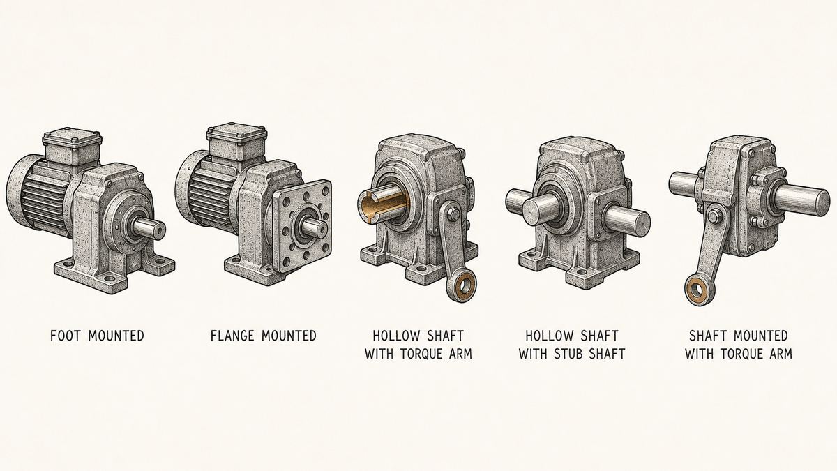
Foot mounting. The unit sits on feet and is bolted down to a base or a bracket. The reaction torque is taken by the bolts and by the base, which is the arrangement the gearbox was designed around, and it is the easiest to get right. It is also the arrangement that fails when the base is thin, when the bolts are short, or when the unit is bolted down on one foot and left to hang on the others. Two things belong in the specification: the shaft centre height above the feet, because it decides how the machine lines up, and a flat, stiff base, because a gearbox bolted to a flexing plate will move every time the machine starts.
Flange mounting. A machined face with a ring of holes bolts flat against a matching face on the machine. It saves the base, it lines up the shaft automatically if both faces are true, and it is the standard answer when the unit hangs off the side of a tank or a frame. What it needs is a flat mating face and the right bolt circle, and those two are worth stating numerically rather than leaving to a picture. A flange that is bolted to a face with a burr or a weld spatter under it will sit crooked, and a gearbox sitting crooked wears its seals and its bearings from the first day.
Hollow shaft. The output is a tube rather than a shaft: the driven machine's own shaft passes straight through the middle of the gearbox, and the drive is taken by a keyway in the bore. There is no coupling, no alignment job and no second set of bearings, and that is why hollow shaft units dominate on conveyor head shafts. The bore and the keyway are the whole specification: a bore that is a fraction large will rattle and wear the keyway out, and a bore that is a fraction small will not go on without heat. Ask for the bore size, the tolerance and the keyway dimensions on the drawing, and confirm whether the unit has a shrink disc or a plain key.
Torque arm. A shaft-mounted gearbox carries its own weight on the driven shaft and needs something to stop it turning around that shaft, and that something is a torque arm. The arm takes the whole reaction torque, so it is a load-bearing part and not a steady stay. It should be fitted with a flexible end — a rubber bush at the eye is the usual answer — because a rigid arm fighting a moving machine transfers shock straight into the gearbox housing. Two mistakes are common here. The arm is fitted slack, so the unit rocks and works its mounting loose. Or the arm is bolted to something that flexes, so the gearbox is being pushed round by its own drive.
Shaft-mounted with a solid stub. The same hollow unit can be supplied with a short solid shaft pushed through the bore and keyed in place, which turns it back into a conventional output shaft for a machine that does not have one of its own. It is a useful option and it is not a free one, because the stub and the bore are a second joint that has to be tight and keyed properly.
Two rules close the section, and both of them come from the rulebook rather than from experience. A machine designed to stay in one place has to be anchored, because an unanchored machine walks — and a gearmotor is the part of a machine most likely to make it walk, since a foot-mounted unit pushes its reaction torque into the base every time it starts. And anything on the output side that turns has to be guarded, including the coupling between the gearbox and the machine it drives. Both points are covered in the section on the rules below, with the exact wording, because both are things a buyer can put on an order drawing and settle once instead of arguing about later.
Oil, Seals and Why the Mounting Position Decides Both
A gearbox is filled with oil to a level that suits one mounting position. Turn the unit on its side, stand it on its end, put it on a wall, and the oil that was covering the gears runs somewhere else. It does not leak out and it does not disappear; it simply moves to a part of the housing where it does nothing, while the gears it was meant to protect run dry. This is the least visible failure in the whole subject and the one that produces the most surprising failures.
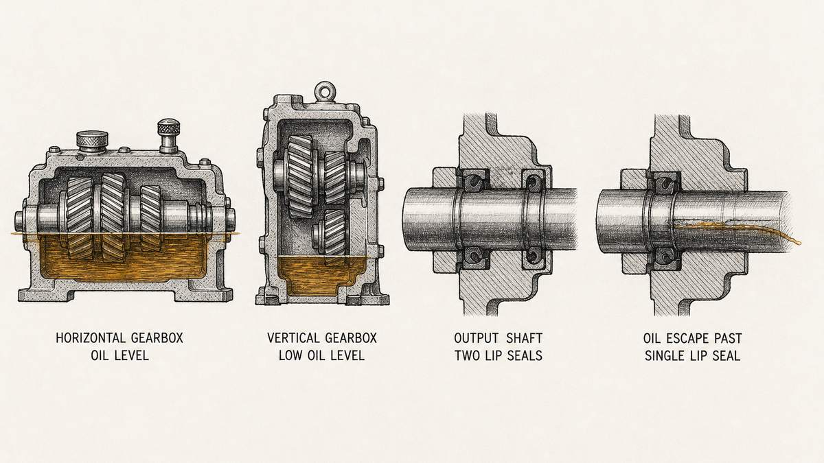
The oil level line is a line for one position. Draw a horizontal line across the housing at the correct level and you can see the problem immediately: the line depends on which way up the box is. Lie the unit flat and the pool covers the lower gear wheels properly. Stand the same unit up and the same volume of oil now sits at one end of the housing, below the wheels at the other end. Nothing is broken. The unit is simply not being lubricated, and it will run quietly for weeks before it says so.
This is why mounting position is not a drawing detail but an order line. Suppliers publish a set of mounting positions — usually lettered or numbered — and the oil quantity, the position of the level plug, the position of the drain plug and the position of the breather all change with the position chosen. Buy two identical gearboxes for two different machines, mount one on a wall and one on a floor, and if both were filled for the floor, one of them is running dry inside.
Three plugs, and all three move when the mounting changes. The filler is where oil goes in and the level plug is where it stops; on many small units they are the same plug and the oil is filled until it reaches the hole. The drain plug must be at the lowest point of the housing in the mounted position, or you can never get the old oil out. And the breather must be at the top, or the housing cannot breathe as it warms and cools. A gearbox delivered with its breather in the wrong place will push oil out past its seals as it warms up, which is why so many oil leaks are not seal faults at all.
The breather is the part buyers forget to fit. Some units ship with a plain plug in the breather hole for transport, and a small breather in a bag. If the plain plug is left in place, the housing becomes a sealed box, the air inside expands as the unit warms, and the pressure pushes oil out of the first weak point it can find. The instruction sheet says to swap the plug for the breather. On a busy installation line, that is a step that gets skipped, and the buyer then blames the seal.
A lip seal is a wearing part, and it wears the shaft too. The output shaft passes out through the housing, and a lip seal presses against it to keep the oil in. Two things shorten its life: dirt arriving at the lip from outside, and a shaft surface that is rough or worn. Over a long life the seal's own contact and any grit it holds will cut a shallow groove into the shaft, and once that groove exists, a new seal will leak as well as the old one. A supplier who offers a hard chrome or sleeved seal surface under the lip is offering something real, and it is worth paying for on a gearbox that runs every day.
Two seals rather than one is a construction choice. A single seal keeps oil in. A second, outward-facing seal keeps water and dust out, which matters on a machine that gets washed down. Some units add a small grease chamber between the two. When a buyer asks whether a gearbox is suitable for a wash-down area, that is the question being answered, and it is a question about seal arrangement rather than about the housing material.
Three oil rules are worth carrying to every order. State the mounting position, because the fill quantity depends on it. Ask what grade of oil the unit is filled with and write it in the manual, because topping up with the wrong grade is more common than running low, and mixing two incompatible oils produces a sludge that blocks nothing and lubricates nothing. And ask for the oil change interval and the first-change interval separately, because many makers specify a short first change to flush out the running-in debris, then a long interval after that. A plant that follows the long interval from new is throwing away the first oil at the worst possible moment.
The Rules a Gearmotor Has to Meet Where It Is Used
There is a whole category of gearmotor problem that has nothing to do with the gearbox and everything to do with what surrounds it, and the rules for that are written down, free to read, and specific enough to be put straight onto an order drawing. They come from two places. The motor's efficiency is a federal energy rule, and the installation — the guarding and the anchoring — is a workplace safety rule. A buyer who brings both to a supplier gets a different conversation.
The efficiency rule, in one paragraph. The standards are in 10 CFR 431.25 and the words used in them are defined in 10 CFR 431.12. The standard applies to a motor made “alone or as a component of another piece of equipment”, so it follows the motor into a gearmotor. It applies to general purpose motors and takes definite purpose motors, special purpose motors and motors exempted by the Secretary back out. And the same section defines what a buyer should be asking for as proof: a certificate of conformity is defined there as a document issued by a certification program that gives written assurance that a motor meets the efficiency standard that applies to it. That is the paperwork line to put on the order. Not a catalogue page, not a badge, a certificate, and it should name the standard.
Two limits on that, so nobody over-reads it. A certificate covers a motor, not a gearbox, and it will not cover the gearbox losses or the claims made about the assembled unit. And this article is not legal advice about a particular machine — it is a map of where the requirements are written down, so that a buyer can read the section that applies instead of trusting a summary. The two sections together take under twenty minutes to read on the electronic Code of Federal Regulations.
Then there is the installation rule, and this is the half nobody quotes. 29 CFR 1910.212 covers general requirements for machines, and it opens with a sentence that a gearmotor buyer should read slowly: “One or more methods of machine guarding shall be provided to protect the operator and other employees in the machine area from hazards such as those created by point of operation, ingoing nip points, rotating parts, flying chips and sparks.” Rotating parts. A gearmotor's output shaft, its coupling and any pulley or sprocket on it are rotating parts, and they are in the machine area. The guard also has to be fixed to the machine where that is possible, and it must not be a hazard in itself — a guard with a sharp edge or a snagging corner is its own problem.
The same section has the sentence that costs plants the most money, and it is eleven words long: “Machines designed for a fixed location shall be securely anchored to prevent walking or moving.” A gearmotor is a machine's drive, and a foot-mounted unit puts its reaction torque into its base every single time it starts. Bolt it to a plate that is not itself fixed, or sit it on resilient pads on a smooth floor, and it will move. Every start it takes moves it a little, the coupling comes out of line, and a year later the gearbox is being blamed for a bearing failure that started with a sliding base plate.
The third rule is the one written for the gearmotor's own output shaft, and it is unusually precise. 29 CFR 1910.219 covers mechanical power-transmission apparatus, and it says that “Projecting shaft ends shall present a smooth edge and end and shall not project more than one-half the diameter of the shaft unless guarded by nonrotating caps or safety sleeves.” One more line follows it, and it is the one that catches more installations than any other: “Unused keyways shall be filled up or covered.”
Read those two sentences against a real gearbox and the practical content jumps out. A gearmotor output shaft that sticks out further than half its own diameter has to carry a non-rotating cap or a safety sleeve. A keyed shaft supplied with no mating part on it — the spare unit on the shelf, the second output of a double-shaft unit, the machine being built in stages — has an open keyway on a spinning shaft, and an open keyway with a key in it is a small projecting blade turning at output speed. The cheapest possible way to deal with both is to specify a smooth, chamfered shaft end and to fit a non-rotating cap when nothing is coupled to it, and both of those are things you can ask a factory for on the drawing.
Two more from the same two sections are worth having in front of you, because they are free details that make a request look professional. In 1910.212, if the machine has a fan with its blades less than seven feet above the floor, the blades have to be guarded and the guard openings may be no larger than half an inch — which matters when a gearmotor drives a fan on a low frame. And the anchoring requirement applies to the machine, so a gearmotor supplied with a mounting bracket should be supplied with a bracket that can actually be bolted down, with holes that clear the bolts and feet that are flat. A bracket with an odd hole pattern becomes an anchored machine's weakest link.
Four Rules That Touch a Gearmotor, and Where Each One Is Written
| The requirement | What it says, in plain words | Where it comes from |
|---|---|---|
| Motor efficiency | A general purpose motor has to meet a published efficiency figure, and the rule follows the motor into a gearmotor | 10 CFR 431.25, with the words defined in 431.12 |
| Proof of efficiency | The document to ask for is a certificate of conformity issued by a certification program | Definition in 10 CFR 431.12 |
| Guarding rotating parts | Rotating parts in the machine area have to be guarded, and the guard must not be a hazard itself | 29 CFR 1910.212(a) |
| Anchoring and shaft ends | A fixed machine has to be anchored, a shaft end projecting more than half its diameter needs a cap or sleeve, and an unused keyway has to be filled or covered | 29 CFR 1910.212(b) and 1910.219(c)(4) |
What to Put in the Specification Sheet
A gearmotor enquiry that arrives as a power figure and a ratio produces a quotation that cannot be compared with anything. A gearmotor enquiry that arrives as a filled specification sheet produces a quotation you can check, and it takes about twenty minutes to write. The general discipline is the same as for any part covered by a drawing, which is set out in this guide to a how a Chinese workshop wants a part written up, and a gearmotor adds its own short list on top.
The output side comes first, because it is the side the machine sees. Output speed in rpm at the stated mains frequency; output torque at that speed in newton metres or pound-inches, and whether that figure is the running torque or the peak; the ratio; and whether the speed has to be held accurately or only approximately. State the mains voltage, the phase and the frequency on the same line, because output speed depends on them and a quotation that names a speed without a frequency has named nothing.
The duty comes second, and most enquiries leave it out entirely. Hours of running a day; starts per hour; whether the machine can jam or stall; whether the load reverses; and whether the unit has to hold its position with the power off. Five short answers change the size of the gearbox, and a supplier who receives them can size with a service factor instead of guessing.
The motor comes third, with its own list. Power in kilowatts or horsepower; voltage, phase and frequency; number of poles; mounting arrangement; enclosure type — a fully enclosed fan-cooled motor for a dusty floor, an open motor only where the air is clean; insulation class; and whether a brake is needed. Add two lines that buyers rarely write and always need: what the motor has to do in the first second of movement, because a loaded conveyor starting against a full belt needs a different motor from one starting empty, and whether the machine is going into a wash-down or wet area, which decides the enclosure and the seal arrangement.
The mounting comes fourth, numerically. Foot, flange, hollow shaft, or shaft-mounted with a torque arm. Then the numbers: shaft centre height above the feet for a foot mounting; the flange size and the bolt circle for a flange mounting; bore size, tolerance and keyway for a hollow shaft; and the length and eye size of the torque arm. Add the position the unit will be mounted in, and say it in words as well as on the drawing — horizontal, vertical, wall — because the oil supply depends on it.
The output shaft comes fifth. Diameter and length, keyed or plain, keyway size, and how much of the shaft will be left projecting with nothing coupled to it. That last line is what turns the rule about projecting shaft ends and open keyways into a supply requirement, and it costs nothing to write.
Then the commercial lines, which are shorter than people expect. Colour and finish, and where the finish must not be applied — a painted shaft or a painted mounting face is a nuisance on the line. The nameplate content: the maker's name, the model, the ratio, the output speed, the motor details and the serial number, and for the motor, the efficiency figure the federal rule applies to it. The documentation that must travel with the crate: the motor's certificate of conformity, the assembly drawing with dimensions, and the oil grade and quantity. The packaging, and whether the shaft has to arrive with a protective sleeve and a non-rotating cap. And the quantity, because the price of the first order is the price of a batch and the price of the twentieth is the price of a repeat.
One habit makes the whole sheet work, and it is the same habit that matters on anything where a small change is invisible after assembly.Keep a signed copy of the approved specification as the reference for the order, in the same way a plant holds a first article for a part where a substitution is invisible. And keep the nameplate photograph of the first unit that arrives. Ratios and speeds are hard to check on a finished gearbox and easy to check against a sheet of paper.
Checking a Gearmotor Before It Ships
A gearmotor is a machine rather than a part, so it can be run. That is the difference between checking a gearbox and checking a plate of steel, and it is why an incoming check on a gearmotor should include ten minutes with the unit powered up. The wider sequence, and how much of a shipment to inspect, is set out in this guide to the pre-shipment inspection step; the gearmotor-specific list is short.
Run it, and run it in both directions. A unit that turns by hand may still be noisy, hot or wrong in one direction under power. Run it at the rated voltage and frequency, in both directions, and listen at the housing rather than at arm's length. A gearbox that is quiet turning one way and grumbles turning the other has a tooth or a bearing problem, and it will not improve.
Measure the output speed. Mark the output shaft, run the unit, and time a known number of turns. On a unit with an accurate ratio, the measured speed should land within a few per cent of the quoted figure at that frequency. This single check catches the two commonest quotation errors — a ratio that is close but not what was ordered, and an output speed quoted for the wrong mains frequency — and it takes less time than reading the nameplate.
Measure the current the motor actually draws. With a clamp meter on the supply, a motor running at the rated load should draw a current in the region of its nameplate figure. A motor drawing substantially more with nothing on its output is either miswired, wrongly connected for the supply, or mechanically stiff, and every one of those is better found in a factory than on a customer's floor.
Feel the housing and the motor frame after a run. Warm is normal. Too hot to hold a hand on for long, on a unit running unloaded, is not, and it usually means the oil is wrong, the level is wrong, the mounting position does not match the fill, or the bearings were fitted too tight.
Look at the oil before you look at anything else. Drain a little from the drain plug. Fresh oil is clean and the colour the grade should be. Oil with a metallic sheen in it means something inside was already running against something else during a test run at the factory. Check the level yourself rather than trusting the mark on the plug, and check that the breather is fitted and not still the transport plug.
Check for leaks at both ends and around the flange faces. Wipe the unit dry, run it warm, and wipe it again a few minutes later. A thin film is normal on a newly filled unit; a wet track running down from a seal or a joint is a fault, and it should be fixed before shipping rather than discussed after arrival.
Then the paperwork and the outside of the part. The nameplate should carry the maker, the model, the ratio, the output speed, the motor details and a serial number, stamped or engraved rather than printed on a sticker that will fall off. The motor's certificate of conformity should be with the crate if it was ordered. The key should be fitted or bagged and tied to the unit rather than loose in the bottom of a carton, where it will be lost. And the shaft should arrive protected, with a cap or sleeve on the free end so that neither the shaft nor anybody's hand is exposed while the unit is being moved and stored — which is the same requirement the installation rule will impose on you later.
Two habits make the rest of the list cheaper. Photograph the nameplate, the oil level and the drain plug position before the crate is closed, because those three photographs settle most arguments about whether the unit that arrived is the unit that was ordered. And keep one unit from the first batch as the reference for the ones that follow, because the delivery that is six months later is the one where the ratio quietly changes.
The Four Failures, and Which Side Each One Is On
Almost every dead gearmotor has one of four things wrong with it, and the four split cleanly into two pairs. Two of them were built into the unit and arrive with it, which makes them a supplier conversation. Two of them are created by the way the unit was mounted and run, which makes them yours. Telling the two pairs apart before you telephone anyone is what decides whether the call is a claim or a lesson.
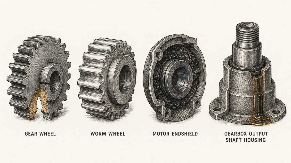
Broken teeth, which arrive with the unit. Two adjacent teeth are gone at the root, the break faces are bright and grainy, and every other tooth is untouched. That pattern is a signature. A tooth that broke because the gearbox was too small for the duty tends to break at the root and take neighbours with it, because the load was being carried on one or two teeth instead of being shared. A shop that finds this fault is looking at a gearbox that was either under-sized at the quotation stage or made from the wrong material, and the two are told apart by whether the rest of the teeth show any wear at all. Clean, unworn survivors around a fresh break point to something that should not have broken.
Worn worm wheel teeth, which also arrive with the unit. The teeth are flattened and thinned almost to smooth stubs, the metal is polished bright, and the hub is untouched. A worm wheel is made from a bronze alloy chosen for its sliding behaviour against a hardened steel worm, and a wheel that has worn itself smooth in a short time was made from the wrong alloy, or the worm was not hardened, or the wrong oil was used from new. This is the one gearbox failure that can look like old age on a young unit, and the tell is the date on the nameplate against the amount of wear.
A scored and blued bearing in a motor endshield, which is usually built by the way the machine is run. The bearing race is scored, the metal has taken a blue tint from heat, and the grease around it has gone hard and black. Blue means heat; heat in a bearing means either it was starved of grease, it was fitted too tight, or it was carrying a load it was never sized for. Two of those are the plant's: a shaft misaligned on installation, and a belt or sprocket hung on the output shaft that pulls the bearing sideways. On a gearmotor the side pull is the one to check first, because a large pulley on a small output shaft is a load nobody wrote down and the bearing takes all of it.
Oil past a hardened, cracked and flattened seal, which is also built by the mounting and the running. The seal has lost its shape, the lip is hard, and there is a track of oil running down the outside of the housing. Three ordinary causes: no breather, so the housing pressurised itself as it warmed and pushed oil out of the weakest point; a mounting position that does not match the oil fill, so the seal sits below the real oil level; and a shaft surface worn into a groove under the lip, in which case a new seal will not fix it. Only one of the three is about the seal, and that is why replacing the seal and putting the unit back is such a common disappointment.
Six Faults and Which Side Each One Is On
| The fault | What gives it away | Whose side it is on |
|---|---|---|
| Output speed wrong at the mains frequency on the order | A measured output speed outside a few per cent of the quoted figure, with the ratio intact | The supplier's if the frequency was stated; yours if the machine runs on a different supply from the one quoted |
| Oil leak in the first days of service | A wet track from a seal or a joint, with the transport plug still in the breather hole | The supplier's if the breather was not supplied or not labelled; yours if it was left in its bag |
| Teeth broken soon after start-up | Two or more teeth gone at the root with the rest unworn | The supplier's, and the likely cause is a gearbox sized on running torque with no service factor |
| Heat and noise after a few months | A housing too hot to hold, dark oil, and the mounting position not the one the unit was filled for | Yours, unless the mounting position on the order was ignored |
| Bearing failure in the motor or the output end | A scored race, a blue tint from heat, and a pulley, sprocket or coupling hung on the shaft | Yours if the side pull was never calculated; the supplier's if the overhung load limit was exceeded as ordered |
| Unit walking, moving or coming out of line | Shiny rub marks under the feet, loose bolts, a base plate that flexes | Yours, and it is the fault that costs the most for the least money to prevent |
The way to use that table is to write down two things before making any claim: the measured output speed at the supply the machine actually runs on, and the mounting position the unit is in against the position it was filled for. Those two lines settle the first two rows without any argument, and between them they explain a surprising share of everything else on the list. The row worth the most money over a plant's life is the last one, because an unanchored drive does not fail in a way that looks like an installation fault — it fails in a bearing, six months later, and looks like a gearbox problem.
Price, MOQ and Lead Time: What Actually Moves the Number
This article does not quote prices, because a gearmotor price without a ratio, a torque, a mounting and a motor attached to it is not information. What it can do is name the things that move the number, so that when two quotations differ by a third you know which question to ask rather than which supplier to distrust.
Which family the gearbox belongs to. This is the biggest single driver and the one least visible in a quotation, because two units quoting the same ratio and the same output torque can be a worm unit and a planetary unit and can differ by a multiple in price. A worm unit gets a large ratio from one pair of parts and costs little to make; a planetary unit gets its rating from shared load and precision and costs a great deal. If a quotation looks too cheap, the first question is which family is being offered, not whether the ratio is honest.
Whether the motor is general purpose or one of the excluded categories. A general purpose motor has to meet a published efficiency figure, and meeting it takes copper and magnetic steel. A definite purpose or special purpose motor sits outside those tables. Sometimes that is real engineering — the motor genuinely is built for one machine and one frame — and sometimes it is a convenient label on an ordinary motor. The efficiency figure and the certificate of conformity are how you tell, and neither costs the supplier money to produce if the motor really is what it claims. This is the same pattern as any part where the honest version and the cheap version look identical from outside; a the sprocket that drives a gear motor bought on tooth count alone behaves the same way.
The gears themselves: cut, ground, or moulded. Cut teeth are the industrial standard. Ground teeth are quieter, more accurate and more expensive, and they are what a buyer is paying for on a servo application. Moulded plastic gears are real and legitimate in small units where the load is light, and they are also what a buyer gets when a metal gearbox is quoted at a plastic price — the same choice that faces anyone ordering the gears inside a gear motor for a mechanism, where a material change is invisible until the load arrives.
The housing and the bearings. A cast iron housing is stiffer, quieter and lasts longer than a cast aluminium one, and it costs more to make and more to ship. Inside, a bearing with a known maker's name is a real cost line, and a quotation that lists no bearing brand has left that line open. On a gearbox that runs every day this is not a detail; it is the part of the unit most likely to end its life.
The motor's real specification. Enclosure type, insulation class, whether a brake is fitted, whether the motor is a standard frame or a special one built to fit the housing, and how the motor is cooled. Each of those is a genuine difference in the part. So is the supply: a motor wound for a voltage and frequency that is not the common export one costs more, and that extra cost is not a markup.
Seals, breathers and the small parts that decide whether the oil stays in. A double seal arrangement, a hardened or sleeved seal surface under the lip, a proper breather and a drain plug in the right place are each a small line on a good quotation. On a gearbox these lines are the difference between a machine that stays dry and a machine that marks its floor for years, and they are the first things removed when a price has to be cut.
Mounting and shaft work. Drilling and tapping a flange, machining a hollow bore to a stated tolerance with a keyway, and supplying a torque arm are all machining operations rather than catalogue picks. They are also where an odd hole pattern or a non-standard bore quietly turns a standard unit into a special one, which changes both the price and the lead time.
Quantity, and the shape of the order. Gearboxes are made in batches and assembled to order, so the price per unit falls with quantity and the first unit of a new size carries most of the setting up. This is the reason a single special unit looks expensive and the twentieth identical unit looks cheap, and it is the same pattern for anything that has to be set up before it can be made. Two commercial habits follow. Ask for the price at three quantities, because the setup content is visible in the gap and it tells you what a repeat order will cost. And buy one spare before you need it, because a gearmotor that fails takes a production line with it, and the second unit is always cheaper than the first.
Lead time moves for reasons that are worth asking about in the same breath as price. A standard ratio in a standard housing from stock is a different timescale from a special bore, a non-standard voltage or a special frame motor. Ask which parts of the unit are stock and which are made to order, and ask for that answer in writing, because a delivery date given for a stock unit and applied to a special one is how a project slips three weeks without anybody lying.
Questions Buyers Ask
How do I work out the output speed and torque I need?
Work backwards from the machine rather than forwards from the motor. Decide the speed the machine has to run at, then work out the turning effort it needs at that speed. Divide the motor's speed by the output speed you want and you have the ratio. The torque then follows from the power, because power is torque multiplied by speed and the gearbox only trades one for the other. Two figures are worth adding: the torque needed to start the machine when it is fully loaded, which is often higher than the running torque, and whether the machine can jam. Send the output speed, the output torque, the ratio, the mains frequency and the duty, and the supplier is sizing a real machine instead of a shape.
Does the fifty or sixty hertz difference really matter on a gearmotor?
Yes, and it is the single most common technical error in the trade. Motor speed comes from the mains frequency and the number of poles and nothing else, so the same motor turns about twenty per cent faster on sixty hertz than on fifty. The gearbox ratio is unconnected, so the output speed moves with the motor. Run a unit quoted for fifty hertz on a sixty hertz supply and the machine runs fast, the motor draws more current, and the torque at the shaft at a given output speed is lower than the quotation suggested. The way to close it is one line on the order: state the voltage, the phase and the frequency, and ask the supplier to confirm the output speed at that frequency in writing.
What oil should I use, and can I just use what we already have?
Use what the gearbox maker specifies, and write it down in your maintenance record. Gear oil is not interchangeable between units: the grade and the additive package are chosen for the tooth geometry, the materials and the temperatures the unit will see, and a worm gearbox in particular will not tolerate the wrong grade, because its whole life depends on a sliding oil film. Mixing two compatible-looking oils can produce a sludge that neither lubricates nor drains. Ask two questions on the order instead of one: the oil grade and quantity, and the first oil change interval separately from the regular one, because many makers specify an early first change to flush out running-in debris and a much longer interval after that.
Can I mount a gearbox in any position I like?
You can mount it in any position it was specified for, and the specification is the point. The oil sits in the bottom of the housing, so the position decides which parts of the gearing are in the oil. Suppliers publish a set of mounting positions, and the correct oil quantity, the level plug, the drain plug and the breather all change with the position chosen. Mount a unit filled for a horizontal position on a wall and the oil runs to one end while the gears at the other end run dry — and it will run quietly for weeks before it fails. Two things follow: state the mounting position on the order in words as well as on the drawing, and check that the drain plug will be at the lowest point once the unit is mounted, or you will never get the old oil out.
Why would the motor inside need its own paperwork?
Because it is a separate regulated product with its own rules. In the United States the definitions sit in 10 CFR 431.12 and the standards in 10 CFR 431.25, and the standards apply to a motor made “alone or as a component of another piece of equipment” — which reaches the motor inside a gearmotor. The same section takes definite purpose motors, special purpose motors and motors exempted by the Secretary back out of its first four tables. What you ask for is the nameplate efficiency figure, the category the motor falls into, and a certificate of conformity, which the same rules define as a document issued by a certification program giving written assurance that a motor meets the efficiency standard that applies to it. A supplier who understands the question answers it from records; a supplier who has never been asked usually cannot answer it at all, and that is useful to know before the order rather than after.
How do I tell a gearbox factory from a trader?
Ask five things and read how the answers arrive. What tooth geometry is being offered, and can the drawing show the ratio stage by stage. What material and heat treatment the gears and the worm are made from, with the hardness range in writing. What bearing brand is fitted, and whether that brand is in the price. What the housing material is, and whether the oil quantity changes with the mounting position. And what the overhung load limit is on the output shaft. A gearbox works answers all five from its own drawings and does not need to ask anyone. A trader answers the ratio, the price and the delivery date and refers the rest upstream, which is a perfectly good answer when it is given openly and a warning when it is not.
Send the output speed and the duty — not just the motor power
Tell us what the machine has to do, then the lines that decide whether the gearbox survives: the output speed at your mains voltage, phase and frequency, and the output torque at that speed; the ratio; the hours a day it runs, how often it starts and whether the machine can jam; the mounting type with its numbers — shaft centre height, flange bolt circle, hollow bore size and tolerance with the keyway, or the torque arm length; the position the unit will be mounted in, because the oil quantity follows it; the motor's power, voltage, phase, frequency, poles, enclosure and insulation class, and whether it needs a brake; which family of gearbox is being offered, because a worm unit and a planetary unit are not the same product at the same ratio; the tooth material and heat treatment, the bearing brand, and the overhung load limit on the output shaft; whether the shaft end is to be keyed or plain and how much will be left projecting with nothing coupled to it; and the oil grade, the first-change interval and the regular interval. If a unit has already failed, describe what you see: whether teeth are broken at the root and whether the rest are worn, whether the oil is dark or carries a metallic sheen, whether a bearing has gone blue with heat and whether anything is hung on the output shaft, whether the seal is hard and cracked, and whether the breather is fitted and the mounting position matches the fill. The pattern usually says whether the fault was built into the gearbox or built by the way the machine runs.
Request a Gear Motor Sourcing Quote
Questions & Comments
We read every one and reply within 24 hoursA gearmotor is quoted on power and ratio, and it lives or dies on the duty cycle, the mounting position and the motor that is inside. Tell us what the machine has to do, and we will settle the whole drive before the first quote.