
Thermal Oxidizer Manufacturer: Sourcing RTO, Recuperative and Catalytic Units From China
 ·
Updated October 13, 2026
·
28 min read
A thermal oxidizer is a furnace that burns the solvent and the smell out of an air stream. It is bought on the flow, the solvent loading and the destruction efficiency the plant has promised, and it is accepted or rejected on something else entirely: whether the unit the factory built can hold the operating limit the plant signed for, and whether the plant's own maintenance crew can reach everything a rule tells them to inspect. Those two things are decided at the drawing stage, and they are the two things a quotation almost never shows.
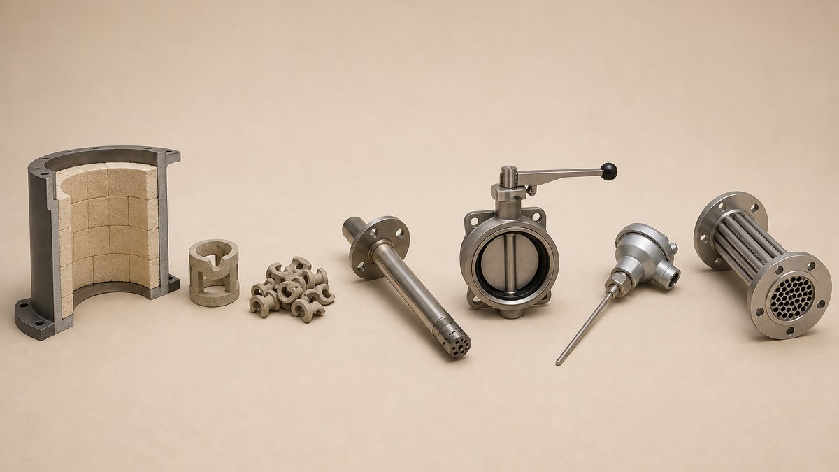
Six Lines That Decide Whether an Oxidizer Order Is Complete
| What the buyer has to settle | Why it is not obvious | The line on your order that closes it |
|---|---|---|
| What the efficiency number has to be measured against | The rule fixes how many runs, how long each one lasts and which test method applies, and the method depends on the expected outlet reading | Destruction efficiency with the test method and the number of runs written beside it |
| Where the temperature probe sits | The rule names the position, and it is a mechanical choice you pay for but rarely state | Probe location in the firebox or immediately downstream before any substantial heat exchange |
| What the operating limit actually is | It is an average taken across the test, not a figure printed on a nameplate | The averaging period, the alarm point and the trip point, each stated |
| Which heat recovery is inside the price | No recovery, an exchanger, ceramic beds and a catalyst bed are four different machines | The type by name, with the recovery medium and the maker of the bought parts |
| Whether the factory can be inspected after it is closed | The plant will be held to a list of ten things a maintenance crew has to look at | Doors, ports and removable insulation at every item on that list |
| What the plant does with a spare catalyst bed | A replacement that is not like or better forces a fresh stack test | The catalyst spec sheet and the maker's name, filed with the order |
What a Thermal Oxidizer Manufacturer Actually Sells You
An oxidizer factory usually builds the vessel, the frame, the duct spools and the refractory. It buys the burner, the ceramic media or the catalyst, the control valves, the instruments and the control panel. Which of those it buys and which it makes is the first thing to settle, because it decides the price, the lead time and who answers when something does not work on site.
The machine splits into three blocks, and they fail for different reasons.
- The destruction chamber
- The lined vessel where the burning happens, plus the burner that holds the temperature and the refractory that protects the steel. This block decides whether the exhaust is destroyed. Its failures are thermal: spalled lining, a burner that will not hold its setting, a shell that runs a hot spot.
- The heat recovery block
- Nothing, a metal exchanger, two or three beds of ceramic shapes, or a catalyst bed. This block decides how much fuel the plant burns and, on a catalytic unit, at what temperature the burning happens. Its failures are mechanical and chemical: fouled tubes, crushed media, a poisoned or channelled catalyst.
- The control and safety package
- The temperature probes, the pressure taps, the recording device, the valve set, the gas train and the burner management logic. This block decides whether the plant can show what it did. Its failures are quiet, and they are the ones that turn into a reportable problem.
Most enquiries only describe the first block. The flow and the solvent come through, the buyer asks for a price, and the three blocks come back as one number with one line of description. That is how a plant ends up owning a machine that destroys the solvent perfectly and cannot produce a three-hour average in the format anyone wants to read.
One practical consequence worth knowing before the enquiry goes out: an oxidizer is a pressure vessel in everything but name where the ducting meets it, and the duct between the process and the oxidizer moves. If the process runs hot and then shuts down, the duct grows and shrinks, and something has to take it. On most installations that is an expansion joint sized for the duct movement, and it is nearly always bought late, sized badly and left out of the oxidizer scope.
The Four Types, and Which One the Rule Picks
There are four arrangements in common use, and the difference between them is only where the heat goes after the burning is finished.
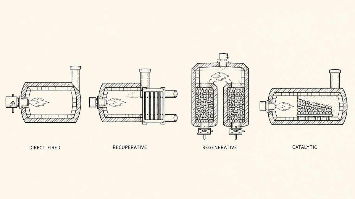
- Direct fired
- The gas is burned and leaves. Simple, cheap to build, expensive to run, and the only sensible choice when the solvent itself supplies most of the heat or when the stream runs rarely. Nothing to foul and nothing to break, which is worth a great deal in a plant with no maintenance crew.
- Recuperative
- A metal exchanger — usually a shell and tube bundle or a plate pack — takes heat out of the clean exhaust and puts it into the incoming dirty gas. Efficient at steady flows, and it keeps the recovered heat in a metal part that can be inspected and, in principle, cleaned. It fouls when the stream carries anything that condenses, and the bundle is the part that fails.
- Regenerative
- Two or more beds of ceramic shapes store the heat and give it back when the flow is switched through them. The valves switch every few minutes, and a purge step clears untreated gas out of a bed before it turns around. Highest recovery of the four, most moving parts, and the type most often chosen for high flow with low solvent.
- Catalytic
- A bed of catalyst lets the burning happen at a lower temperature than a flame needs. Lower fuel, less lining wear, and a new failure mode: the catalyst can be poisoned, coated or channelled, and it costs more per cubic metre than ceramic media. It is not a fit for every stream.
The choice is usually presented as a matter of payback, and on a new plant it partly is. But on a plant that already has a permit, the choice is often already made by a figure in the plant's own paperwork, because the rule that applies to that plant sets the operating limit the machine has to hold, and some limits are only reachable with one of the four. A buyer who asks a factory to quote all four and pick the cheapest has usually asked the wrong question.
Two supporting parts of the line are bought from other factories and are worth naming in the enquiry because they are on the critical path. On a wet process where the exhaust is loaded with dust as well as solvent, the dust is taken out before the oxidizer, and the sludge from the water side has to go somewhere — a filter press closing the loop on that sludge is a separate order from a different supplier. If the dust is dry, the collection hopper needs an auger under it, and a screw conveyor sized for the dust's own flow is what usually sits there.
Where the exhaust comes from matters too, because the oxidizer is being asked to clean up after a process, and the process's own equipment sets the stream it sees. On a drying line the exhaust is made by a drum, and the moisture and the temperature it leaves at are set by the rotary dryer's own moisture basis and its signed inlet ceiling, not by the oxidizer. Getting that number wrong is the most common reason an oxidizer comes back undersized.
What a Destruction Efficiency Figure Has to Mean
Every oxidizer quotation carries a percentage. It is the destruction or removal efficiency, usually shortened to DRE, and it says how much of the organic material going in does not come out. On its own the number means nothing, because it is the result of a test, and a test is only comparable with another test if both were run the same way. One federal rule sets out that way in a level of detail no supplier's brochure will give you.
The rule is 40 CFR 63.3166, and it opens by fixing the whole shape of the test:
“You must conduct three test runs as specified in § 63.7(e)(3), and each test run must last at least 1 hour.”
Three runs, an hour each, minimum. Then the rule says how the samples are taken, and this is the sentence with commercial weight:
“Measure total gaseous organic mass emissions as carbon at the inlet and outlet of the add-on control device simultaneously, using either EPA Method 25 or 25A of appendix A-7 to 40 CFR part 60, as specified in paragraphs (b)(1) through (4) of this section. You must use the same method for both the inlet and outlet measurements.”
Simultaneously at both ends, and the same method at both ends. A test that samples the inlet on Monday and the outlet on Tuesday is not this test, however carefully it was done. Then the rule decides which of the two methods applies, and it decides it from a figure the plant has to predict in advance:
“Use Method 25 if the add-on control device is an oxidizer and you expect the total gaseous organic concentration as carbon to be more than 50 parts per million by volume (ppmv) at the control device outlet.”
“Use Method 25A if the add-on control device is an oxidizer and you expect the total gaseous organic concentration as carbon to be 50 ppmv or less at the control device outlet.”
Finally the arithmetic, which is deliberately blunt:
“Determine the emission destruction or removal efficiency of the add-on control device as the average of the efficiencies determined in the three test runs.”
Read as a buyer, four consequences fall out of those paragraphs.
First, the number is an average of three runs, so a bad run is not something you can argue away. A unit that passes comfortably twice and misses once has not passed. This matters when a factory offers a design margin, because the margin has to cover the worst of three days, not the best.
Second, the expected outlet figure picks the test method, and the two methods are not the same job. Predicting more than 50 ppmv as carbon at the outlet brings Method 25 into play; predicting 50 or less brings Method 25A. The prediction is made before the test and it decides which instrument is brought to site. A buyer who never asks who made that prediction is buying a machine whose acceptance test has been chosen by the supplier's own estimate of its own performance.
Third, the test needs hardware on the duct, at both ends. The same section fixes how the sampling sites are chosen and what is measured during each run, and the requirements are not limited to the stack. Under the same rule, the sampling sites and traverse points are selected using Method 1 or 1A; gas flow is measured with Method 2, 2A, 2C, 2D, 2F or 2G; gas analysis for dry molecular weight uses Method 3, 3A or 3B; stack gas moisture uses Method 4; and “methods for determining gas volumetric flow rate, dry molecular weight, and stack gas moisture must be performed, as applicable, during each test run.” Every one of those needs a port of the right size in a straight run of duct with a reachable platform, and because inlet and outlet are sampled at the same time, the inlet duct needs them too. On a Chinese-built skid that is the most commonly missing item in the scope, and adding it after the ducting is installed and insulated is expensive.
Fourth, if two devices are working in series, both get measured. The rule states that where two or more add-on control devices handle the same stream, emissions are measured at the outlet of each; its own example is a concentrator feeding an oxidizer, where the oxidizer outlet and the dilute outlet of the concentrator are both tested. A plant that adds a concentrator to raise the solvent strength going into the oxidizer has just added a second test location.
Before the enquiry goes out, three questions turn all of this into a price difference: who predicts the outlet concentration for the test method, which sampling ports and platforms are inside the supply, and who pays for the stack test itself. A quotation that answers those three is worth more than one that quotes a percentage in larger type.
The Operating Limit Is an Average, Not a Number
Once the machine has passed its test, the plant has to keep it in a state that would pass again. That state is written as an operating limit, and the way the limit is worked out surprises most people who have not read it. The rule here is 40 CFR 63.3167, and its first instruction about a thermal oxidizer is about where the instrument goes:
“During the performance test, you must monitor and record the combustion temperature at least once every 15 minutes during each of the three test runs. You must monitor the temperature in the firebox of the thermal oxidizer or immediately downstream of the firebox before any substantial heat exchange occurs.”
Two things are being fixed there, and both of them are steel rather than paperwork. The reading has to be taken every 15 minutes or more often, which decides the recorder. And the probe has to sit in the firebox, or downstream of it before any substantial heat exchange. Put the probe after the heat exchanger and you are reading a cooler number that no longer represents the firebox, which is the number the rule asked for. Where the probe sits is a welded boss in a lined vessel, so it is settled on the drawing and not in the field.
Then the limit itself:
“Use all valid data collected during the performance test to calculate and record the average combustion temperature maintained during the performance test. This average combustion temperature is the minimum 3-hour average operating limit for your thermal oxidizer.”
Not the set point, not the design temperature and not the highest reading seen during the test. The average of the valid data, expressed as a 3-hour average, is the floor. The plant's habit of reporting a single spot reading suddenly needs a device that can produce a rolling three-hour average, and the alarm has to be set against it.
The section then offers an alternative for older plants, and it is worth reading closely because it looks like a straight discount and is not:
“If you use 28 degrees Celsius (50 degrees Fahrenheit) below the combustion temperature maintained during the performance test as the minimum operating limit for a thermal oxidizer, then you must keep the combustion temperature set point on that thermal oxidizer no lower than 14 degrees Celsius (25 degrees Fahrenheit) below the lower of that set point during the performance test for that thermal oxidizer and the average combustion temperature maintained during the performance test for that thermal oxidizer.”
Take a moment with that. The route is only open at all to a unit whose latest operating or construction permit, issued before April 26, 2007, already carries temperature recordkeeping and reporting consistent with the thermal oxidizer requirements in 40 CFR 60.395(c). Having got there, the plant is allowed to set the minimum at 50 degrees Fahrenheit below the test average — and then has to keep the set point no lower than 25 degrees Fahrenheit below the lower of two numbers: the set point used during the test, and the average temperature maintained during the test. The limit drops by more than the set point is allowed to drop. The gap between the two is the room the machine is given to wander, and it is narrower than it first appears.
For a buyer, that whole mechanism comes down to four items that have to be on the drawing rather than in the manual. The temperature probe's location, written by position, not by a note that says “in the oxidizer.” The recorder's interval and its averaging window. The alarm point. And the trip point, which is a different decision again, because a trip that stops production during a short cool spell costs money that no permit requires.
One more consequence of the word average. A three-hour average limit is not an instantaneous one. A unit can sit under its target for a few minutes and still hold the average, which is why the way the machine behaves at part load matters more than the way it behaves at its rated point. Turndown is not a comfort feature; it is what the averaging window is there to permit.
Catalytic Units and the 80 Percent Rule
A catalytic oxidizer does the same job at a lower temperature, and the rule handles it with two instruments instead of one. The same section requires the plant to record the temperature just before the catalyst bed and the difference across it, every 15 minutes through each of the three runs. The limit then comes out of both readings:
“The minimum 3-hour average operating limits for your catalytic oxidizer are the average temperature just before the catalyst bed maintained during the performance test of that catalytic oxidizer and 80 percent of the average temperature difference across the catalyst bed maintained during the performance test of that catalytic oxidizer, except during periods of low production, the latter minimum operating limit is to maintain a positive temperature gradient across the catalyst bed.”
And low production has its own definition, which is unusually specific:
“A low production period is when production is less than 80 percent of production rate during the performance test of that catalytic oxidizer.”
So there are two floors, not one. The pre-bed temperature has to stay at the level it saw during the test, and the rise across the bed has to stay at four fifths of what it was. When the line runs below four fifths of its test rate, the second floor changes shape: it becomes a requirement that the bed still shows a positive rise, because a catalyst with no rise across it is not working, whatever the inlet temperature says.
This is the single most useful thing a buyer can know about a catalytic quotation, because it means the two thermocouples around the catalyst bed are not optional extras or monitoring conveniences. They are the instruments that generate the number the plant reports. If a quotation lists “temperature monitoring” without saying that there are two probes, one before the bed and one after it, the control package is not designed against the rule.
The same section also writes the maintenance the plant will owe, and for a catalytic unit three items are named:
“Annual sampling and analysis of the catalyst activity (i.e., conversion efficiency) following the manufacturer's or catalyst supplier's recommended procedures.”
“Monthly external inspection of the catalytic oxidizer system, including the burner assembly and fuel supply lines for problems and, as necessary, adjust the equipment to assure proper air-to-fuel mixtures.”
“Annual internal inspection of the catalyst bed to check for channeling, abrasion, and settling.”
Channeling, abrasion and settling: three ways a catalyst bed quietly stops working. Channeling is gas finding a path through and leaving the rest of the bed cold. Abrasion is the surface wearing away and going out with the exhaust. Settling is the bed compacting and opening a gap past itself. None of the three shows up on a temperature reading until it is well advanced, which is why the rule asks for a yearly look inside rather than a continuous instrument.
The last paragraph of that group is the one to carry into procurement:
“If the catalyst bed is replaced and is not of like or better kind and quality as the old catalyst, then you must conduct a new performance test to determine destruction efficiency according to § 63.3166. If a catalyst bed is replaced and the replacement catalyst is of like or better kind and quality as the old catalyst, then a new performance test to determine destruction efficiency is not required and you may continue to use the previously established operating limits for that catalytic oxidizer.”
Like or better avoids a fresh stack test; different does not. A plant that buys a replacement bed from a second supplier on price, without a spec sheet it can compare against the original, has taken on a test it may not have budgeted for. This is a reason to file the catalyst maker's data sheet with the original order and to write the replacement condition into the maintenance file — the same reason it is worth naming the product specification sheet the factory signs against in the enquiry rather than leaving the beds to be described verbally.
Where Regenerative Capacity Hides: Beds, Valves and the Purge
A regenerative oxidizer earns its lower fuel bill by storing heat in ceramic and giving it back. Dirty gas rises through one bed that is still hot from the previous cycle, passes through the combustion chamber, and then travels down through the second bed on its way out, heating that bed as it cools. A few minutes later the valves turn and the two beds swap jobs. Nothing about the burning has changed; only the direction of travel has.
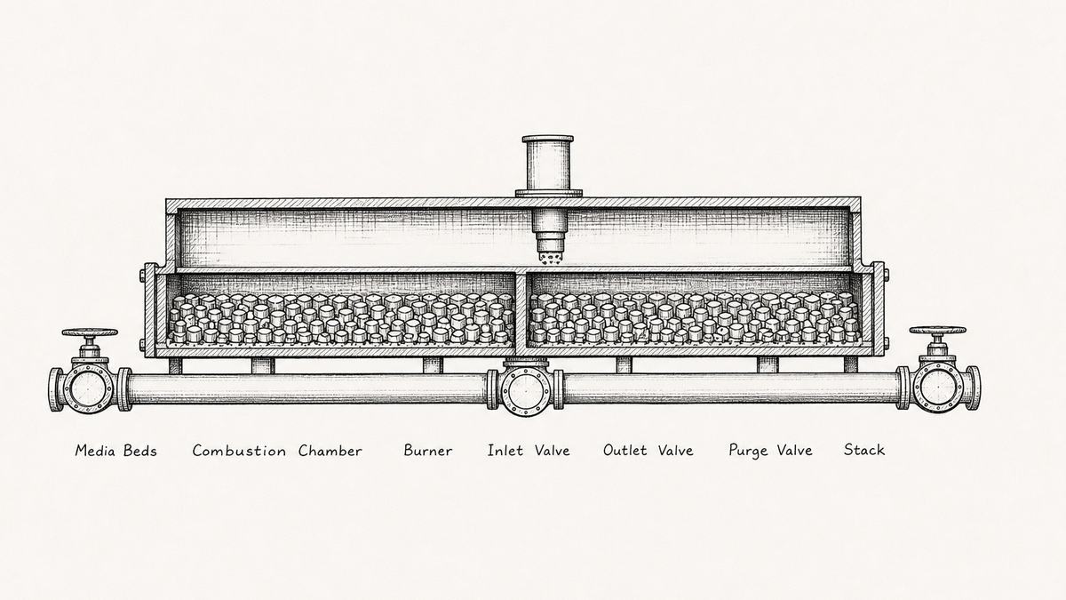
Between those two states sits the step that decides whether the machine works, and it is the one buyers never ask about. When a bed finishes its turn as the outlet, it is full of clean gas — but the ducting above it and the space inside it still hold untreated gas from the moment before the switch. Turn the valves without clearing that out and the untreated gas goes straight up the stack on the next cycle. The purge is what pushes it back into the chamber first, and it is the third valve in the figure for that reason.
A purge that is too small is the same as no purge. Its size is a volume, not a feature, so the enquiry should ask for the purge volume and the time allowed for it, and the answer should be a number the factory chose on purpose rather than whatever space was left in the sequence.
The valve set is the part of a regenerative unit that carries the cycles. A unit switching every three minutes runs through its valves more than a hundred thousand times a year, and the seals are what give out. Two seal designs are common, and the choice is a trade rather than a free upgrade: an elastomer-seated valve shuts tighter but is limited by temperature, and a metal-seated valve survives hotter duty but passes more. Ask which one is quoted. A regenerative oxidizer with a leaking inlet or outlet valve looks healthy from the control room — the chamber temperature is right, the burner is firing normally, and the stack reading is quietly high.
The media is the other half of the same story, and it is where a cheap quotation usually hides. Random shapes — saddles, rings and balls tipped in loose — cost less per cubic metre, sit at a higher pressure drop, and can be topped up when they break down. Structured blocks in a monolith give a much lower pressure drop and a smaller vessel, cost more, and cannot be patched. Underneath both choices is the material, and the material has to survive two things at once: repeated heating and cooling, and whatever the burned solvent turns into. A chlorinated solvent leaves an acid that eats the wrong ceramic, and a stream with sulphur does the same thing more slowly.
None of that shows up until it does, which is why one instrument belongs in every regenerative scope: a differential pressure tap across each bed. Fouling raises the drop, broken media changes it, and either way the reading moves before the stack does. On a recuperative unit the same tap belongs across the exchanger bundle. A quotation that lists the vessel, the media and the burner but no pressure taps has left out the only instrument that reports what the beds are doing.
One more thing about the beds. They are where everything the process failed to catch ends up. Whatever enters as gas and is not destroyed lands on the ceramic, and material that is sticky or has a high boiling point will land on it and stay. That is a pre-treatment problem rather than an oxidizer problem, and it is worth settling which device is doing the catching. On a stream that carries dust as well as solvent, the wet route is sometimes the answer further up the line, and a wet scrubber sized to the dust load rather than the gas volume is the device that takes it out before the ceramic sees it.
The Burner, the Flame Arrester and the Gas Train
The burner on an oxidizer has one job, and it is not to be efficient. Its job is to hold the chamber at the temperature the plant has promised, through every change in the process upstream, including the changes that happen while nobody is watching. Two figures describe whether it can: its turndown, which is how far below full fire it can run and still be stable, and the range of the control valve that sets the gas to it.
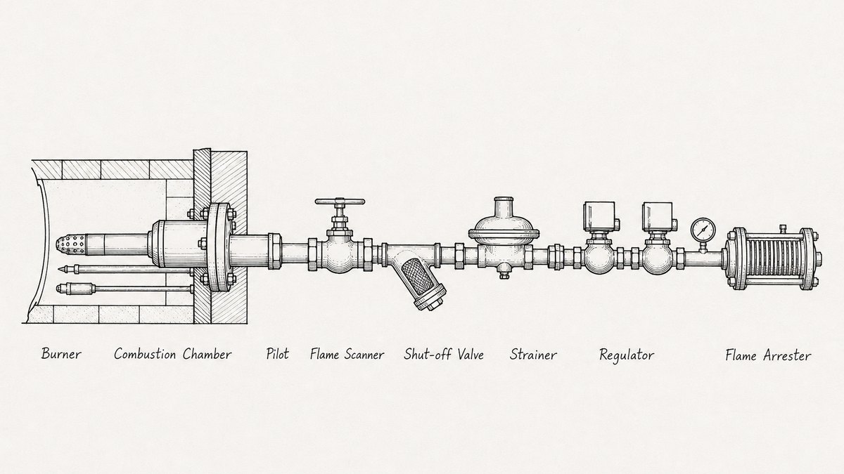
Around the burner sits the safety chain, and it is worth asking for it in writing because it is built from logic rather than steel. Before ignition the chamber is purged with air, and it is purged by volume rather than by feel — a set number of chamber volumes, every start, enforced by the control system. Then the pilot lights and is proved, then the main flame lights and is proved by a scanner watching the chamber, and then the main gas stays open only while that proof holds. A flame failure has to shut the gas within seconds. None of this is optional equipment and none of it is visible in a photograph of the skid, which is why it belongs on the datasheet as a sequence with times rather than as a line that says “PLC controlled.”
The gas train in the figure is standard in shape and specific in detail. A manual shut-off valve so a person can isolate the line. A strainer, because a regulator that swallows grit stops regulating. A regulator to bring the supply to the pressure the burner is set for. Two automatic shut-off valves in series, with a tightness test between them, because one valve that sticks open is a path for gas into a chamber that may be hot. A pressure switch to prove the gas is there, and a second one to prove it is not too high. A gauge, because somebody will want to know.
The flame arrester sits on the waste gas side rather than the fuel side, and it is the part most often left out of a quotation. Where a stream carries enough solvent to burn on its own — a coating line, a printing press, a laminator — a flashback down the duct toward the process is a real event rather than a theoretical one. The arrester is a housing full of narrow passages that pulls the heat out of a flame front and stops it travelling. Whether one is needed is decided by the solvent loading and the oxygen in the stream, so the enquiry has to say what is in the gas. A factory that quotes an oxidizer for a heavily loaded stream without asking about flame arrest has not read the stream.
Two questions take the guesswork out of this block. Which parts does the factory make and which does it buy, with the maker's name for each bought item. And what is the gas train's sequence on start-up and on trip, written as steps with times. A quotation that answers both is a quotation from a factory that has built these before.
The Instruments You Are Signing Against
The instrument list is the shortest part of a quotation and the part that decides whether the machine can be shown to work. Every figure the plant reports comes off one of these, and each one has one job.
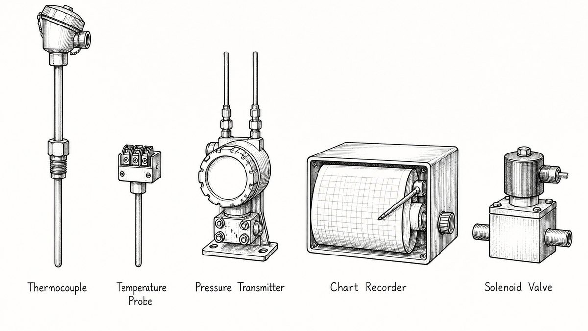
- Combustion temperature probe
- Sits in the firebox or immediately downstream of it and before any substantial heat exchange, because that is the position the rule names. Its reading, averaged over three hours, is the operating limit.
- Pre-bed and post-bed probes
- Only on a catalytic unit, and there are two of them because the limit needs both. The pre-bed reading gives one floor and the difference between the two gives the other.
- Differential pressure transmitter
- One tap across each ceramic bed, or across the exchanger bundle on a recuperative unit. This is the instrument that reports fouling and broken media before the stack tells you.
- Capture flow or duct static pressure
- On the collection side, upstream of the oxidizer. It shows that the exhaust is still being captured at all, which is a separate question from whether it is being destroyed.
- Recorder
- The device that keeps the record. It has to be able to produce a rolling three-hour average and to hold the record for as long as the plant's permit requires, which makes it a logger with an export rather than a roll of paper.
Two details turn that list into something useful. The first is range. A probe bought to cover the whole possible temperature band reads a 600 degree limit badly, and a limit read badly is a limit argued about. The range should be set around the window the plant actually cares about, and the calibration certificate should come with the machine rather than being bought later.
The second detail is that the averaging period and the retention period are decisions, not defaults. A recorder that samples once a minute and averages over an hour will not produce the three-hour figure without somebody doing arithmetic by hand, and a logger that overwrites after thirty days cannot support a claim about last quarter.
This block is also the cheapest line to cut and the most expensive to add back. The instruments themselves are not the cost; the welded bosses, tapped flanges and cable trays they need are, and those are made during fabrication. An instrument added after the vessel is lined and the ducting insulated means cutting into finished work. That is the reason to insist that the instrument list, the tag numbers and the drawing agree before the first plate is cut — the same reason a first article inspection before the run continues is worth more on this equipment than on almost anything else in the category.
What the Inspection Rule Makes the Factory Build In
There is a second rule that matters more to the buyer than the first, and it is not about how the machine performs. It is about whether a person can get inside it. One federal rule sets out, in ten numbered items, what a plant has to inspect on its own thermal oxidizer every year, and the list reads like a description of a machine that was designed to be looked at.
The rule is 40 CFR 63.2987, and the opening sentence is the one that carries the obligation:
“If you use a thermal oxidizer, the maintenance schedule must include procedures for annual or more frequent inspection of the thermal oxidizer to ensure that the structural and design integrity of the combustion chamber is maintained.”
The ten items follow, and they are worth reading as a buying specification rather than as legal text, because every one of them is a question about the drawing:
- “Inspect all burners, pilot assemblies, and pilot sensing devices for proper operation. Clean pilot sensor if necessary.”
- “Ensure proper adjustment of combustion air and adjust if necessary.”
- “Inspect, when possible, all internal structures (such as baffles) to ensure structural integrity per the design specifications.”
- “Inspect dampers, fans, and blowers for proper operation.”
- “Inspect motors for proper operation.”
- “Inspect, when possible, combustion chamber refractory lining. Clean and repair or replace lining if necessary.”
- “Inspect the thermal oxidizer shell for proper sealing, corrosion, and hot spots.”
- “For the burn cycle that follows the inspection, document that the thermal oxidizer is operating properly and make any necessary adjustments.”
- “Generally observe whether the equipment is maintained in good operating condition.”
- “Complete all necessary repairs as soon as practicable.”
Two of the items begin with the words when possible — the baffles and the refractory lining — and that phrase is doing real work. It is an escape hatch for a machine that cannot be opened, granted to the plant in advance. A factory that designs for reachability turns those two items into something the crew can actually do, and the way it does that is unglamorous: an access door on the right face of the chamber, a removable section of insulation rather than a continuous jacket, a platform at the height a person will be standing, and a lining anchored so that a repair can be patched rather than rebuilt.
The rest of the list is about serviceability. The burner assembly has to come out for item one, which means the flange, the gasket and the clearance around it have to allow that. Combustion air adjustment has to be reachable and visible, which means the damper is not buried behind a panel. Fans, blowers and motors have to be somewhere a person can stand and listen to them.
Item seven is the one buyers should carry to the drawing review. A shell inspected “for proper sealing, corrosion, and hot spots” is a shell a person has to be able to see, and on a lined vessel the shell is covered by insulation. If the insulation is a sealed jacket that has to be cut open to look at the steel, the inspection will not happen and the plant will record it as done. The design decision that prevents that is a shell band left open or a jacket built in removable panels.
Two things are worth saying plainly about the source. Those figures come from the subpart that covers one industry's drying and curing ovens — formaldehyde from friction materials manufacturing — and the sections about the efficiency test and the operating limit come from the subpart covering surface coating of automobiles and light-duty trucks. Neither set of figures is a general legal limit, and a plant in another industry answers to whatever rule applies to it, which may be none. What travels between industries is the shape of the requirement. A buyer who has no rule to answer to can still put these ten items into the enquiry and ask the factory to show, on the general arrangement drawing, that each one is reachable. Whatever the plant's legal position, that is a better machine.
How These Machines Actually Fail
Four failures cover most of what goes wrong, and they split neatly into two that the plant causes and two that come from the choice of parts.
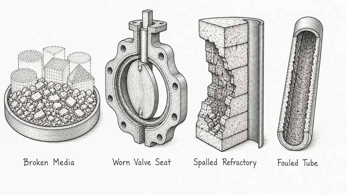
- Broken media
- The ceramic shapes crack and go to pieces. The usual cause is thermal cycling combined with a grade chosen for price rather than for the duty, and the usual consequence is ceramic found in the ductwork and at the fan. The warning is a rising pressure drop across the bed, which is why the tap belongs in the scope.
- Worn valve seat
- On a regenerative unit, the switching valve seals wear and stop shutting tight. The chamber temperature stays correct and the machine sounds normal, while a share of untreated gas goes around the beds and out. The signal is a stack reading that climbs with no change in the process, often with an asymmetric temperature profile between the two beds.
- Spalled refractory
- The hot face of the lining breaks away in flakes and slabs. It comes from heating or cooling the chamber faster than the lining can take, from a castable chosen for the wrong temperature, or from anchors that let go. The signal is a hot spot on the shell and lining debris on the chamber floor — and a hot spot is exactly what item seven of the inspection list is looking for.
- Fouled exchanger tube
- On a recuperative unit, material condenses or collects on the bundle and the recovery falls away. Nothing alarms. The plant simply buys more gas each month until somebody compares two years of bills. It happens when the stream carries something that condenses at the temperature the exhaust leaves at, which is a question about the stream rather than about the machine.
All four are inspectable before the machine leaves the works, and that matters because two of them are decided at the factory. The media grade and shape can be checked against the order. The valve make and its seal type can be read off the nameplate. The lining's thickness and its anchor spacing can be measured on a drawing and again on the finished chamber, and the cured condition can be seen. The shell's roundness at the bed support ring can be measured, which is the dimension that decides whether the beds sit level and the seals run true. And the position of every instrument boss can be checked against the instrument list, because a probe in the wrong place is a machine that cannot produce its own number. That is the case for treating this equipment like anything else in the category and putting a pre-shipment inspection with a measured record in front of the shipping date rather than a set of photographs.
What to Send, and What to Check in the Quotation
A thermal oxidizer enquiry that goes out as a flow rate and a temperature comes back as a price for a box. One that goes out in four blocks comes back as something that can be compared with the next quotation. These are the four blocks, and each one exists because a factory cannot size the machine without it.
Ten Lines a Thermal Oxidizer Enquiry Has to Carry
| What to send | Why the factory cannot answer without it |
|---|---|
| The gas volume, with the temperature it was measured at and whether it is actual or corrected | Every downstream dimension — chamber, beds, fan, ducts — follows from this figure, and a corrected volume and an actual volume at 400 degrees are different machines |
| The contaminant by name, plus its loading and any particle size data | The name decides the ceramic or the catalyst and the materials of construction; the loading decides how much of the heat the gas supplies by itself |
| Whether the stream runs continuously or intermittently | A unit that starts and stops needs a purge and a warm-up its own way, and an intermittent line cannot hold an average the way a continuous one can |
| The destruction efficiency required, with the test method and the number of runs beside it | The efficiency sets the chamber volume and the residence time; the method and run count set the sampling ports and platforms that have to be built into the ducts |
| The combustion temperature the plant has signed for, and who signs for it | This sets the burner, the lining thickness, the air system and the probe position — and a signature makes it a design constraint rather than a preference |
| Whether the operating limit comes from an old permit or a new one | The alternative route is only open to older permitted units, and it changes both the limit and the set-point rule the control system has to enforce |
| The type you want, or the four you want priced | No recovery, an exchanger, ceramic beds and a catalyst are four machines, and a single lump price hides which one is inside it |
| The media or catalyst grade, with the maker's name | A replacement bed that is not like or better forces a fresh stack test, so the original grade has to be on the record from the first order |
| The instrument list with ranges, averaging periods and retention | The operating limit is a rolling three-hour average, and only an instrument ranged and configured for it can produce the number |
| Which items are inside the scope: sampling ports, platforms, fan, ductwork, controls, flame arrester | These are the lines that move between quotations, and they are the reason two prices for the same machine differ by half |
Reading the answers back is quicker than it looks. Check that the moisture and the loading come with their basis stated, and that the factory used the same basis you did, because a wet basis and a dry basis read as a large difference in machine size. Check that the efficiency figure has a test method beside it. Check that the burners, the media or catalyst and the valves all have maker's names, and that the split between what the factory makes and what it buys is written down. Check the list of items excluded from the scope, because that list is where the money is. And check that the operating limit appears as an averaging period rather than as a single temperature, because a single temperature is a design point and not a limit.
How much does a thermal oxidizer cost?
There is no useful average, because the price follows the gas volume, the materials and how much of the equipment is bought rather than made. Two units handling the same flow can differ by a multiple if one is carbon steel with a plain lining and the other is stainless with a catalyst bed, a full gas train, an instrument package and a flame arrester. What a buyer can do is ask for the price broken down by the four blocks: the chamber and its lining, the heat recovery, the burner and gas train, and the controls and instruments. That turns the total into something comparable between quotations. The items that move the number most are the chamber lining thickness and material, the recovery medium — nothing, metal, ceramic or catalyst — the valve make on a regenerative unit, and whether the fan, the ductwork, the sampling ports and the platforms are inside the scope at all. A quotation much cheaper than the others is nearly always cheaper because one of those has been reduced or left out.
What is a thermal oxidizer used for?
It destroys the organic material in an air stream by burning it at a controlled temperature. In practice it is fitted wherever a process releases solvent or odour into exhaust air: coating and painting lines, printing and laminating, adhesive and resin work, chemical and pharmaceutical processing, and food processing where the smell itself is the problem. The machine produces carbon dioxide and water from what it burns. Its reason for existing is usually a permit limit on what may leave the stack, and its reason for being expensive is that holding a high temperature continuously costs fuel unless heat is recovered.
What is an RTO in manufacturing?
RTO stands for regenerative thermal oxidizer, and the regenerative part is about heat rather than about the burning. Instead of a metal exchanger, the unit holds two or three beds of ceramic shapes. The clean hot gas leaving the chamber passes through one bed and heats it; when the valves turn, the incoming dirty gas passes through that same hot bed and is preheated before it reaches the chamber. Heat that would have gone up the stack is stored in ceramic and given back minutes later. That is why an RTO uses far less fuel than a direct fired unit on a large flow. The cost of the saving is moving parts: the valves that switch the beds, and the purge that clears untreated gas out of a bed before it changes duty.
What is the difference between recuperative and regenerative?
Both recover heat from the clean exhaust, and they do it with different hardware. A recuperative unit uses a metal exchanger — normally a tube bundle or a plate pack — and the recovered heat stays in metal parts that can be inspected and cleaned. A regenerative unit uses ceramic beds and switching valves, recovers more of the heat, and brings the valves, the purge and the media into the maintenance picture. Recuperative is often the better choice on a smaller or dirtier stream, because a fouled bundle can be cleaned and does not need to be replaced. Regenerative is usually the better choice on a large, clean, continuous flow, because the recovery is higher and the vessel is smaller for the same duty.
Do I need a catalyst, or can I just burn hotter?
Burning hotter is the simpler machine and it is the right answer on many streams. A catalyst earns its place when the burning temperature has to come down — which reduces fuel, reduces the wear on the lining, and matters a great deal when the stream contains something that would otherwise form nitrogen oxides at high temperature. It costs more per cubic metre than ceramic, and it adds three failure modes that ceramic does not have: the bed can be poisoned by something in the stream, coated by it, or channelled by gas finding a path through. It also adds annual work, because the catalyst activity has to be sampled and the bed has to be looked inside once a year. If a stream is clean and the fuel bill is acceptable, a hot ceramic unit is the more forgiving machine.
How do I know the efficiency claim is real?
By asking how it will be measured. A destruction efficiency figure is the result of a test, and a test is only comparable with another test if both were run the same way: the same number of runs, each of the same minimum length, with the inlet and outlet sampled at the same time and by the same method, and the result taken as the average of the runs. Ask the factory which test method applies to your stream and why, ask who predicted the outlet concentration that chose it, and ask whether the sampling ports and platforms at both the inlet and outlet are inside the scope. Then ask who pays for the test and who is present when it is run. A factory that can answer those four questions in writing has built these machines before. One that answers with a percentage has not answered.
Send the contaminant and the limit — the gas volume alone is not enough
Tell us what is in the exhaust and what the plant has promised. The gas volume with the temperature it was measured at, the solvent by name, the destruction efficiency with its test method, and the combustion temperature the plant signed for. Then the machine, the instruments and the sampling ports.
Request a Thermal Oxidizer Sourcing Quote
Questions & Comments
We read every one and reply within 24 hoursMost oxidizer arguments come down to two figures that were never written down: the destruction efficiency and the test method it will be measured by, and the operating limit the plant has signed for. Send us both, and we will pin them down before the order.